
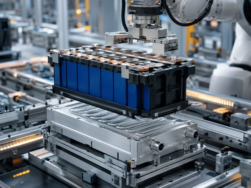
Battery module assembly is the mechanical, electrical, and thermal work of turning matched cells into a serviceable module, and unlike cell production it adds almost no chemistry. Cells arrive already made; the module line sorts them, holds them in a fixture, connects them, and builds in the heat path and monitoring the pack will rely on. The step most engineers underweight is thermal integration: the interface materials, cold-plate contact, and electrical isolation that decide the cell-to-coolant heat path are laid down during assembly, not bolted on afterward. This article walks the assembly sequence in order, then shows where thermal management enters it, how cell format changes the approach, and what a finished module has to prove before it moves to the pack. For teams building standardized or custom battery modules, that sequence is where cooling performance is either designed in or lost.
What Battery Module Assembly Involves
Between the cell and the pack sits the module: a group of matched cells joined electrically, held mechanically, and instrumented enough to be monitored as one serviceable unit. Cells provide the energy, the module makes them handleable and connectable, and the pack combines modules with pack-level controls, cooling loops, and the enclosure. If the distinction matters for your design decisions, settle the difference between battery module and battery pack before you fix module boundaries. That choice decides which functions you build at module level and which you defer to the pack.
What separates module assembly from cell manufacturing is that it is mechanical work: the cell’s electrochemistry is already finished, so what remains is joining, fixturing, insulating, cooling, and wiring. That framing keeps expectations realistic: a module line controls interconnect quality, mechanical retention, isolation, and thermal contact, not cell capacity or chemistry, which are set upstream. Where a module ends and the pack begins is a design choice, not a fixed rule, and settling it early shapes the battery module design and everything the assembly line has to deliver.
The Battery Module Assembly Sequence, Step by Step
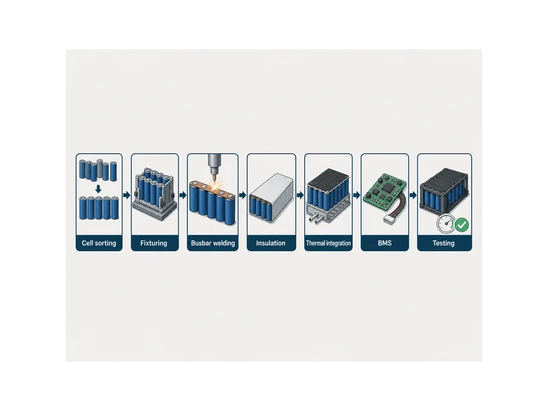
Think of the assembly sequence as a repeatable chain of stages, each one constraining the next, not as a single operation. The order below reflects how most module lines are structured, from incoming cells to a validated module:
- Cell sorting and matching. Cells are grouped by measurable parameters, commonly open-circuit voltage, internal resistance, and capacity, so a module is built from cells that behave alike. Mismatched cells force the weakest cell to set the group’s usable limit, so this step protects both performance and life.
- Positioning and fixturing. Cells are placed into carriers or holders that set spacing and orientation, then retained so the group can withstand vibration and thermal expansion in service. Cylindrical, prismatic, and pouch formats each need different carriers and compression features.
- Busbar welding. Cell terminals are joined to busbars to build the series and parallel connections. Laser welding, ultrasonic welding, and busbar bonding are the common methods; the method that fits depends on terminal material, thickness, and access, and no single one wins everywhere.
- Insulation and protection. Insulating films, barriers, and coatings are added to prevent short circuits between cells and between live parts and the structure. This is also where barriers that slow heat spread between cells are placed.
- Thermal interface and cooling integration. Thermal interface materials, gap fillers, and cold-plate contact are established so heat has a defined path out of the cells. This stage is detailed in the next section because it is where cooling performance is decided.
- BMS integration. The battery management system slave board and temperature and voltage sensing are installed so the module can be monitored and balanced. Sense points have to reach the cells they report on, which is easier to build in now than to retrofit.
- Module-level testing. The finished module is checked electrically and mechanically before it joins a pack, covered in the validation section below.
Two things make this sequence unforgiving. The connections are permanent, so a weld or isolation defect found later usually means scrapping or reworking a whole module instead of a single part. And each stage assumes the previous one held tolerance: a cell seated a fraction out of position changes weld gap, and an uneven surface changes how well a thermal material fills the gap it is meant to fill.
Where Thermal Management Enters Module Assembly
The cell-to-coolant path is not something you bolt on at the pack stage — grasping that is the single most useful thing to understand about it. The interface between the cells and the cooling surface, the material that fills that interface, and the electrical isolation across it are all established while the module is being put together. Once cells are welded and fixtured, the heat path is largely fixed, and there is no convenient later stage to correct a poor thermal contact.
The core requirement at this interface is contradictory on its face: the connection between cells and the cold plate has to be electrically isolated and thermally connected at the same time. Bare metal-to-metal contact would short; a thick air gap would insulate thermally. A thermal interface material resolves this by filling the gap with a compliant, electrically non-conductive medium that still conducts heat, so the cell can reject heat to the plate without a live path to it. Getting that right is a materials-and-fit problem, not a cooling-power problem alone.
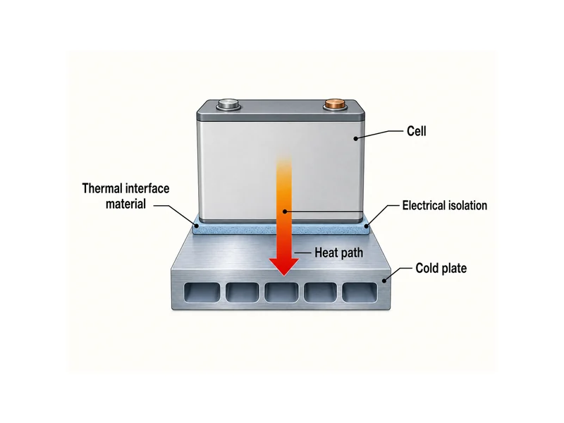
Which interface material fits turns on a handful of assembly variables more than on any headline conductivity number. Gap size and surface flatness set how much material is needed and how well it wets both faces. Assembly stress and the compression the design applies decide whether a firmer pad or a conformable gap filler is appropriate. Whether the material cures, and how long that takes, affects line time and whether the bond also carries structural load. Reviewing thermal pad applications against your own gap, flatness, and pressure conditions is more reliable than matching on conductivity alone, because a high-conductivity material that does not conform to the real surface leaves air where it matters most.
The thermal-integration step is where Trumonytechs’ cold plates and thermal interface materials do their work in the module: the plate provides the cooled surface, and the interface material closes the cell-to-plate gap so the heat actually crosses it. Matching the interface material to the plate and the cell face is an assembly decision, and it is easier to get right when the cooling components and the interface material are selected as a set instead of sourced independently.
How Cell Format Changes the Assembly Approach
Fix the cell format before the line is designed, because it changes almost every downstream assembly choice and is costly to adapt around later. Cylindrical, prismatic, and pouch cells present different terminal layouts, different surfaces to cool, and different retention needs, and each pushes the welding, fixturing, and thermal contact in a different direction. A deeper split by geometry is covered in EV battery module types; the assembly-level consequences are the focus here.
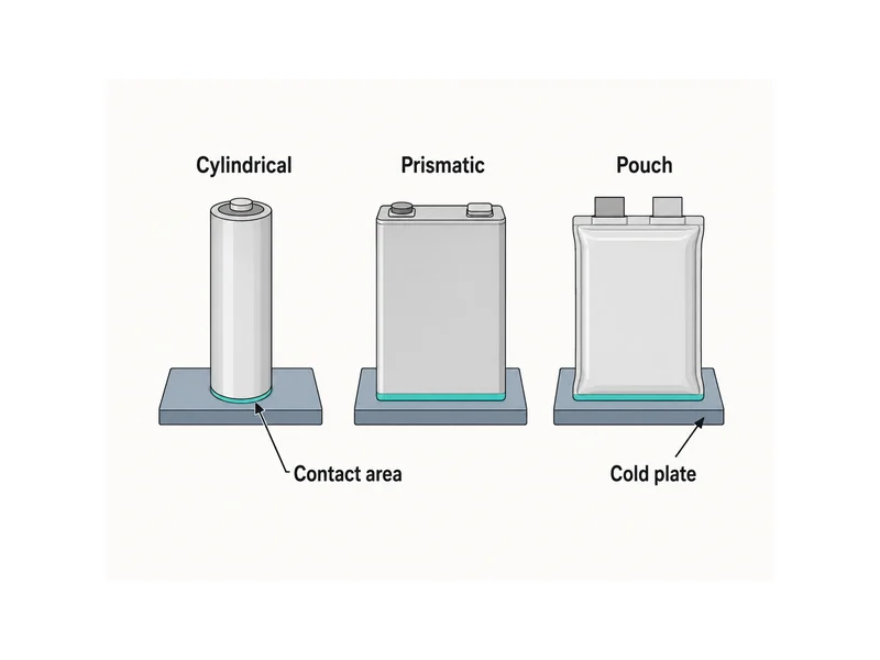
The cooling surface a format offers is often the deciding factor for thermal integration. Prismatic and pouch cells present relatively large flat faces that can sit against a cold plate or a gap filler with good contact area, while cylindrical cells make contact along curved surfaces or through their bases, which changes how the interface material has to be shaped and where it goes. Contact pressure matters here too: too little leaves gaps that trap air, too much stresses cells and interconnects, and the workable pressure window is set by the cell and the material, since no universal figure covers it. Format also drives retention, because pouch cells often need compression to control swelling while hard-case prismatic and cylindrical cells resist it differently.
Validating a Finished Module
Before a module is allowed into a pack, it has to prove electrical, mechanical, and thermal integrity, because defects are far cheaper to catch here than after integration. Testing at this stage typically spans electrical checks such as voltage, resistance, and isolation, mechanical checks for retention and durability, and environmental checks under temperature and vibration. Weld continuity and isolation resistance deserve particular attention, since both are set during assembly and both are hard to inspect once the module is closed.
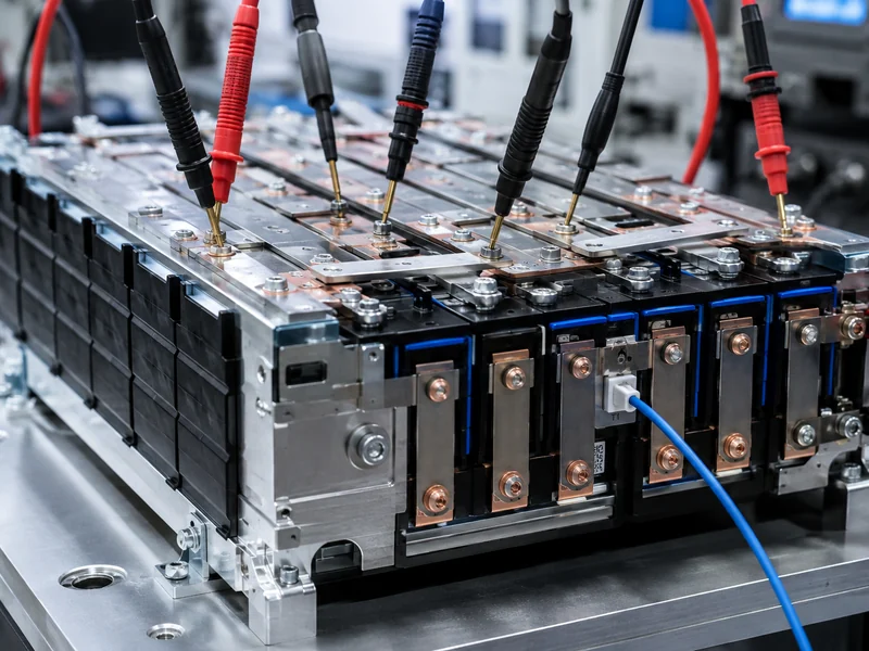
What changes at module level, versus the cell or the pack, is the useful framing for planning these checks, and battery module testing covers that shift in detail. Module tests confirm that the interconnections, isolation, and thermal contact built into this specific assembly actually hold, which the cell tests upstream cannot show and the pack tests downstream assume are already good. Passing at module level does not replace pack-level validation; it removes the assembly-borne failures that would otherwise surface late, when a whole pack is at stake.
Conclusion
The most important thing to take from battery module assembly is that it is one continuous mechanical-electrical-thermal build, and the thermal layer is set during assembly and cannot be added later. Cell sorting protects the group, welding and fixturing make it durable, and the interface material and cold-plate contact decide the heat path while the module is open and correctable. The point most often misread is exactly that timing: teams treat cooling as a pack-level add-on and then find the cell-to-coolant interface already frozen inside a welded module.
For a finished module to cool the way its design intends, the interface between cells and the cooling surface has to be matched to the real gap, flatness, and compression of the assembly, not to a conductivity spec in isolation. That is the variable worth locking first. Trumonytechs works from that heat path outward, matching cold plates and thermal interface materials to the module instead of selecting either in isolation, which is the practical way to keep the thermal contact you designed for through assembly and into service.
FAQ
What steps are involved in assembling a battery module?
Battery module assembly runs from cell sorting and matching, through positioning and fixturing, busbar welding, insulation, thermal interface and cooling integration, and BMS installation, to module-level testing. Each stage constrains the next, and because the connections are permanent, defects usually mean reworking the module, not just a single part.
At what point during assembly is thermal management integrated?
Thermal management is integrated during module assembly, at the point where the interface material, gap filler, and cold-plate contact are established between the cells and the cooling surface. Once the cells are welded and fixtured the heat path is largely fixed, so the thermal interface is designed in during assembly and cannot be retrofitted at the pack stage.
Why is a thermal interface material used instead of direct cell-to-plate contact?
A thermal interface material is used because the cells must be electrically isolated from the cold plate while still rejecting heat to it, which bare metal-to-metal contact cannot do. It fills the gap with a compliant, non-conductive medium that conducts heat, avoiding both a short circuit and an insulating air gap. Whether it needs to cure depends on the specific material and whether the bond also carries load.
Which welding method is used for busbar connections?
Laser welding, ultrasonic welding, and busbar bonding are all used for cell-to-busbar connections, and the fit depends on terminal material, thickness, and access, and no one method is best everywhere. The choice is made against the specific cell and busbar, not assumed from format alone.
How is electrical isolation kept between the cells and the cooling plate?
Electrical isolation between cells and the cooling plate is kept by the interface material and insulation placed during assembly, which separate live surfaces from the plate while still allowing heat to cross. Because both isolation and thermal contact are set at assembly, isolation resistance is verified during module-level testing before the module enters a pack.
Further Reading
- Battery Module: Manufacturing, Assembly and Test Process Flow — Battery Design, a neutral battery-engineering reference. Supports the assembly-then-test sequence described above and gives a wider view of the mechanical process flow.
- Battery Module Manufacturing Process — Electrification Academy, an industry knowledge base. Supports the stage breakdown from cell preparation through electrical connection and BMS, useful for cross-checking the step order.
Related Articles
- What Are The Best Materials To Seal EV Batteries? — How sealing materials keep moisture and contaminants out of an assembled module and protect its internal components.
- Why Battery Protection Matters Electric Vehicle — Why cell, module, and BMS protection matters for EV battery life and safety.
- What Is TEC Cooling? — How thermoelectric (Peltier) cooling creates a temperature difference when you need precise, reversible control.
- How to Choose a Battery Energy Storage System Configuration — How power-to-energy ratio, site limits, and discharge frequency drive an ESS configuration.
- Ceramic Thermal Paste: What It Is, How It Works, and When to Use It — When ceramic-filled thermal grease fits battery gap-filling and where its performance ceiling lies.
