
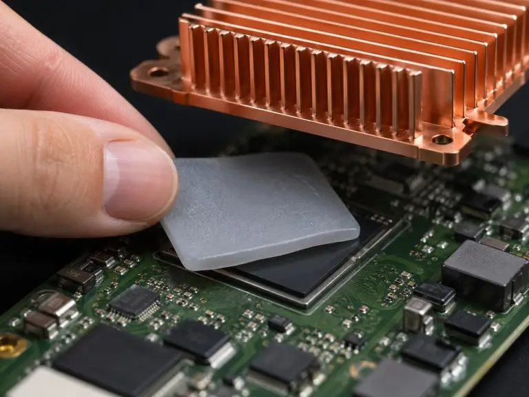
Thermal pads are solid-phase thermal interface materials placed between a heat-generating component and its cooling assembly. The assembly may be a heatsink, cold plate, or chassis wall. Their function is to displace air trapped in micro-scale surface gaps and replace it with a conductive, compliant medium. Three variables determine how well a thermal pad performs: through-plane thermal conductivity, surface conformability under clamping load, and compressed bondline thickness at assembly.
Compared to thermal paste, thermal pads hold their shape better under compression. They are less prone to pump-out during thermal cycling and can be pre-cut for automated assembly. These properties make them the practical choice in high-volume production lines and in sealed assemblies — such as EV battery modules — where reapplication is not an option.
Thermal pads are not a universal substitute for paste or phase-change films. In high-heat-density single-chip interfaces, material type and thickness must be evaluated against the specific thermal budget. Do not select on default assumptions.
The Most Common Misconception in Thermal Pad Specification
A higher thermal conductivity rating does not automatically mean lower junction temperature. This is the most common mistake we see in early-stage pad selection. The thermal pad is one element in a series resistance chain. That chain also includes contact resistance at both interfaces, the heatsink or cold plate resistance, and the ambient cooling capacity. Upgrading pad conductivity while leaving a downstream bottleneck unchanged produces little improvement at the junction.
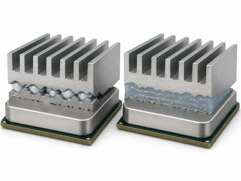
A second failure mode is selecting a pad by its nominal W/m·K value without confirming compressed bondline thickness in the actual fixture. A thicker, softer pad compresses differently than datasheet values suggest. The effective thermal resistance — expressed in most datasheets as gap pad thermal conductivity in thermal impedance terms (°C·cm²/W) — often diverges from the simulation input used during design. In our experience, skipping this check during prototyping typically leads to a pad change or fixture redesign before production release.
The key test reference here is ASTM D5470. It defines the controlled fixture method for measuring thermal resistance under specified thickness and pressure conditions. Vendors including 3M, Parker, and Henkel derive their datasheet values from this or an equivalent method. Before finalizing a specification, confirm that the candidate pad’s datasheet uses a comparable test condition.
Component-Level Uses: VRMs, MOSFETs, Power Modules, and Memory
Thermal pads serve different functions across the power delivery chain, and requirements shift at each stage. Voltage regulator modules (VRMs) generate localized heat under load. They are commonly coupled to a heatsink or chassis via a thermal pad. Pad thickness depends on the gap between the VRM surface and its mating structure — a gap that varies across board generations and must be measured in the assembled state.
Power MOSFETs in motor drives and DC-DC converters generate repetitive thermal pulses from high-frequency switching. Mechanical fatigue resistance matters as much as initial conductivity here. The pad must maintain interface integrity across thousands of expansion and contraction cycles. When qualification relies only on initial datasheet values without long-cycle testing, interface degradation can cause junction temperatures to rise slowly in the field. This is often mistaken for component aging.
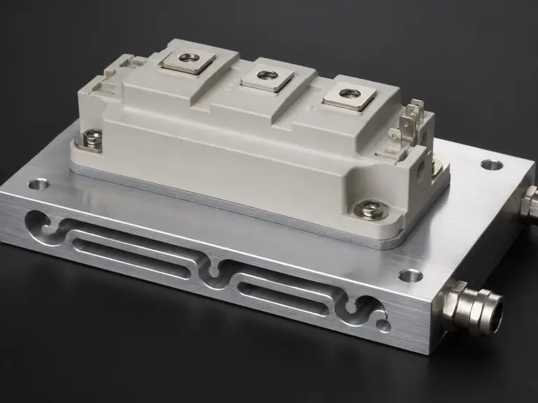
Power modules are among the most demanding thermal pad applications. IGBT module thermal management in inverter stacks — and SiC modules in EV drivetrains — require both electrical isolation and sufficient through-plane conductivity. Isolation performance is characterized under ASTM D149 (dielectric breakdown voltage) and ASTM D257 (volume resistivity). These values must be confirmed at the compressed assembly thickness. Isolation performance decreases as the pad compresses, so nominal thickness values are not sufficient.
Memory modules in servers and networking switches use thermal pads to couple module surfaces to heat spreaders or chassis walls. The main challenge is conformability across multiple chips of varying height on a shared PCB substrate.
For CPU and GPU primary die interfaces in high-performance computing, thermal paste or phase-change TIM films are often preferred. A thinner, more fluid application achieves lower initial thermal resistance. Thermal pads are more commonly used for secondary components — VRAM chips, power stages, M.2 controller packages — where production coverage consistency matters more than minimum thermal resistance at a single die.
Consumer and Commercial Device Applications
In consumer and commercial electronics, assembly consistency and surface coverage take priority over absolute thermal performance. Laptops use thermal pads between CPUs, GPUs, and heatsinks. The chassis gap and pad thickness are engineered together as a matched system. Pad specification is model-specific and must be confirmed against the OEM’s thermal design.
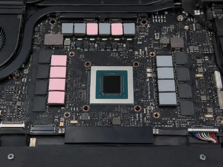
Gaming consoles use thermal pads for processors and memory chips. Pre-cut geometries match the component footprint to ensure consistent production coverage. Smartphones and tablets use thin thermal pads in 5G chipset assemblies and around image processors. Stack-up thickness is tight, so pad selection must balance conformability with minimal compressed bondline.
Servers and data center hardware use thermal pads for memory arrays, secondary PCB components, and chassis coupling. LED lighting assemblies — including high-power architectural fixtures and automotive headlamps — use thermal pads to couple LED chips to metal-core boards or aluminum heat spreaders. This directly affects lumen maintenance over time.
Flammability performance is relevant across most consumer and commercial applications. UL 94 is the standard reference for pad flame retardancy. For many end-product certifications, the interface material’s UL 94 rating is a required documentation item.
Industry Applications: EV Battery, Automotive, and Medical
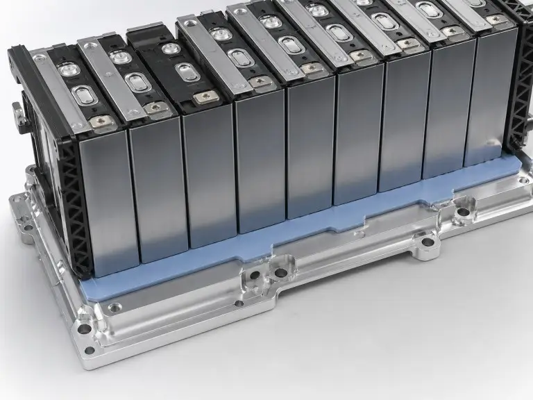
In EV battery modules, thermal interface materials for EV battery modules sit at the cell-to-cooling-plate interface. Key requirements include stable thermal resistance across charge-discharge cycles, uniform compression across cell arrays with varying cell heights, and chemical compatibility with the module environment. Where pad outgassing is a concern in sealed enclosures, ASTM E595 provides the test framework for total mass loss and volatile condensable material.
Automotive electronics — ECMs, power steering inverters, in-cabin compute platforms — operate across wide temperature cycles. Common ranges run from −40°C to +125°C or beyond, depending on the application zone. Vibration loading can cause interface fatigue over service life. Automotive pad qualification requires thermal cycling endurance data, not only initial thermal resistance values.
Medical device applications carry a different constraint set. Where thermal pads sit inside internal electronics with no patient or user contact pathway, biocompatibility requirements may differ from externally exposed materials. The applicable framework is ISO 10993-1. It bases evaluation scope on the nature, duration, and pathway of patient contact — not on device classification. Any thermal pad in a medical assembly must be evaluated within the device’s risk management process. General commercial-grade certification is not sufficient.
The table below summarizes common application categories, their primary requirements, and key qualification standards.
| Application | Primary Pad Requirements | Key Reference Standards |
|---|---|---|
| Power electronics / inverters | Through-plane thermal resistance, electrical isolation | ASTM D5470, ASTM D149, ASTM D257 |
| EV battery modules | Thermal resistance over cycle life, outgassing | ASTM D5470, ASTM E595 |
| Automotive electronics | Thermal resistance, temperature cycle endurance, vibration | ASTM D5470, thermal cycling protocols |
| Consumer / commercial electronics | Thermal resistance, flammability classification | ASTM D5470, UL 94 |
| Medical devices | Thermal resistance, outgassing, biocompatibility pathway | ASTM D5470, ASTM E595, ISO 10993-1 |
Thermal Pad vs. Thermal Paste: When Each Fits the Application
Thermal paste and thermal pads solve the same interface problem through different mechanisms. The right choice depends on power density, assembly process, and serviceability requirements. For a full comparison across application scenarios, see our guide on thermal gap pads vs thermal conductive paste.
Thermal paste achieves lower thermal resistance in high-power single-component applications — bare-die CPUs in workstations, high-wattage GPUs in gaming systems. A thin applied layer conforms more completely to micro-scale surface irregularities than a pre-formed pad. Understanding what thermal paste does at the die interface clarifies why this advantage is strongest where surface flatness is poor and heat flux is concentrated. The trade-offs: paste requires controlled application to avoid voids, is prone to pump-out under thermal cycling, and does not give consistent coverage in automated assembly.
Thermal pads are more appropriate where coverage consistency, clean handling, and predictable geometry matter more than minimum thermal resistance at a single junction. For assemblies requiring electrical isolation, pads with tested dielectric strength values are easier to specify and validate than paste.
A common error is treating thermal pads as a direct drop-in for paste. For primary high-heat die interfaces, validate the substitution against the component’s thermal specification at the expected power level. Meeting the nominal W/m·K target is not sufficient on its own.
Selecting the Right Thermal Pad: Material Type, Key Parameters, and Validation
Thermal pad selection comes down to four variables: through-plane thermal conductivity, electrical isolation requirement, operating temperature range, and compressed bondline thickness at assembly.
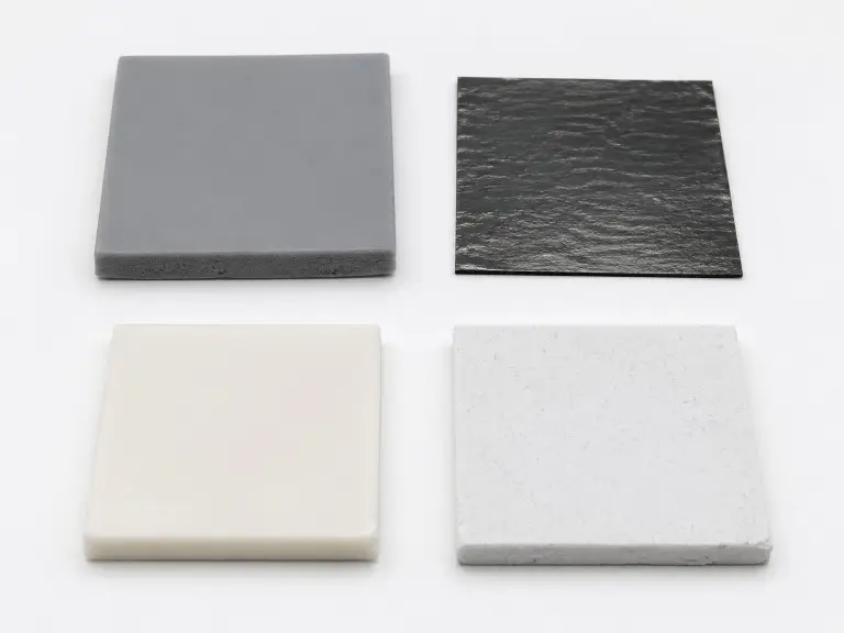
Silicone-based pads are the most widely used across consumer electronics, automotive, and industrial applications. They are flexible, electrically isolating, and conformable to irregular surfaces. Conductivity for common silicone pad products falls in the low-to-mid single-digit W/m·K range. Operating temperature limits and electrical properties vary by product and must be confirmed on the individual datasheet.
For a direct comparison of the two most common options, see our breakdown of graphite sheet vs silicone thermal pad selection. Graphite pads offer higher thermal conductivity but are electrically conductive. Do not use them where isolation is required. One key distinction: graphite’s in-plane conductivity can be an order of magnitude higher than its through-plane value. Heat flows through the pad thickness in interface applications. The through-plane value is the relevant parameter — not the in-plane figure often highlighted in product literature.
Phase-change thermal interface materials soften and flow slightly under heat. This improves surface contact during the first operating cycles. They are common in power module and inverter applications. Conductivity values vary by product and must be confirmed on the datasheet.
Ceramic-filled silicone pads combine moderate conductivity with maintained electrical isolation. They are common in industrial and automotive electronics where both properties are required.
For any pad under evaluation, use thermal impedance (°C·cm²/W or °C·in²/W) at the specified compressed thickness as your primary design parameter. Bulk conductivity alone does not reflect full interface behavior under assembly conditions. Electrical isolation voltage must also be verified at the compressed thickness — not at nominal pad thickness.
Conclusion
Selecting the right thermal pad means evaluating thermal impedance at compressed thickness, electrical isolation under operating voltage, temperature range, and material compatibility — together, not as separate checkboxes. The validation path runs through referenced standards: ASTM D5470 for interface thermal performance, ASTM D149 and D257 for electrical isolation, UL 94 for flammability, and ASTM E595 or ISO 10993-1 for specialized environments.
At Trumonytechs, our scope covers both liquid cooling plates and thermal interface materials. We regularly see the interaction between structural cooling design and TIM specification play out in the same project. In practice, pad performance issues most often arise from interface parameters — compressed bondline, isolation under load, and long-cycle stability — being checked independently rather than as a combined acceptance baseline. We align these variables during drawing review, because gaps found on the datasheet but not in a representative fixture are the ones most likely to require a redesign after tooling is set.
If you are specifying thermal pads for an EV battery module, power electronics assembly, or high-density electronics application, start by sharing your gap tolerances, thermal budget, electrical isolation requirements, and applicable test standards. Our team will confirm material fit and identify which parameters need physical validation at the prototype stage before production quantities are committed.
FAQ
What is the difference between a thermal pad and thermal paste?
Thermal paste achieves lower initial thermal resistance for high-heat single-chip interfaces. A thin applied layer conforms more completely to micro-scale surface variations. Thermal pads are preferable where coverage consistency, clean handling, and defined electrical isolation matter more than minimum thermal resistance at one junction. The right choice depends on power density, assembly process, and serviceability requirements.
Does a higher W/m·K rating always mean better cooling?
No. Thermal pad conductivity is one variable in a series resistance path. If the heatsink, cold plate, or airflow is the limiting factor, upgrading pad conductivity will not reduce junction temperature. Evaluate the full thermal path — not the pad alone — to find where improvement is most effective. Use ASTM D5470 data at the assembly’s compressed thickness as your reference.
Are all thermal pads electrically isolating?
No. Graphite pads and some metal-foil materials are electrically conductive. Do not use them where isolation between a component and a grounded heatsink or chassis is required. Confirm dielectric breakdown voltage (ASTM D149) and volume resistivity (ASTM D257) at the compressed assembly thickness before specifying.
What determines correct thermal pad thickness?
The correct thickness is set by the gap between the component surface and the mating cooling structure in the assembled state. Account for flatness variation across the contact area. Confirm compressed bondline thickness in a representative fixture — do not extrapolate from nominal pad thickness values.
Do thermal pads need to be replaced when a heatsink is removed?
Most thermal pads are one-time-use. After the pad conforms under heat and load, removal creates new gaps that the conformed pad cannot re-seal. Some product families are designed for rework — confirm reuse suitability on the product datasheet before assuming the pad can be reused.
Are thermal pads suitable for EV battery modules?
Yes. Thermal pads are widely used at the cell-to-cooling-plate interface in EV battery modules. Suitability depends on the required thermal resistance for the target cell temperature window, the cell height tolerance range, and material compatibility with the module environment. Evaluate outgassing performance against ASTM E595 where the enclosure design requires it.
