
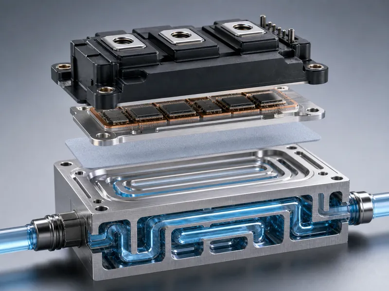
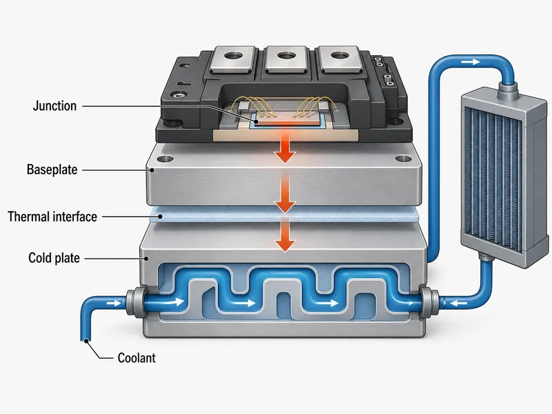
Liquid cooling manages an IGBT’s heat by carrying it from the silicon junction, through the module baseplate and a thermal interface layer, into a cold plate and the coolant loop. Junction temperature is the constraint that ties this path together. It is one of the main limits on usable power density, alongside the safe operating area, transient thermal impedance, and the device’s electrical ratings. Keep the junction inside its design margin and the module switches dependably; let it climb and losses, thermal stress, and aging rise with it. For EV traction inverters, energy-storage converters, and industrial drives, air cooling often runs short of margin before the module does. A well-designed liquid loop earns its place there.
The audience here is power-electronics and battery-pack thermal engineers deciding whether an IGBT needs liquid cooling and, if so, which cold-plate and coolant variables set the result. The scope stays on the cooling problem. Sizing the inverter, gate-drive design, and pack electrical layout are out of scope.
Why IGBT Modules Generate Heat
Two loss mechanisms produce the heat inside an IGBT: conduction loss and switching loss. Conduction loss appears while the device carries current between collector and emitter, where the on-state voltage drop times the current becomes heat in the chip. Switching loss appears during each on/off transition, when voltage and current overlap briefly and the stored energy is released as a heat pulse. Both scale with the operating point. Raise the switching frequency, the bus voltage, or the load current, and the total loss climbs with it.
The practical consequence is that cooling duty tracks the mission profile, not the datasheet headline. A higher switching frequency generally raises switching loss, so a module that stays cool in a steady industrial drive can run hot under a fast-transient traction duty at the same current. Specify thermal management against the real duty cycle, not a single nameplate rating.
How Overheating Limits IGBT Performance and Life
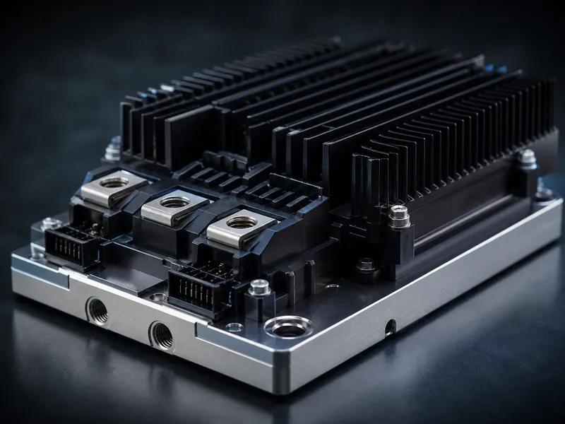
Push the junction past its rated limit and three problems set in together: thermal stress, higher losses, and faster aging. Thermal stress builds across the mismatched materials in the package and shows up over time as bond-wire fatigue, solder-joint cracking, and substrate delamination. Losses rise because the on-state voltage drop increases with temperature. Aging accelerates because most power-module failure mechanisms are strongly temperature-dependent: higher average junction temperature and larger thermal cycles tend to speed up specific failure modes. Actual service life still depends on the mission profile, the thermal-cycle amplitude, and the module’s own life model.
Junction temperature and thermal resistance are defined and measured under IEC 60747-9 and IEC 60747-15, which specify how junction-to-case and case-to-sink resistances are characterized. One published mini-channel cold-plate study held the module case under about 100 °C to protect a 125 °C junction limit on its test bench. Treat that as a single study’s constraint, not a universal number. The applicable case and junction limits must come from the target module’s datasheet; typical silicon IGBT junction limits sit near 125–150 °C.
What a Liquid Cooling Loop for IGBTs Includes
Four components carry IGBT heat from the module out to ambient, and each adds thermal resistance you have to budget:
- Cold plate: bolted or bonded near the module baseplate; its channel design and contact quality dominate how much heat reaches the coolant.
- Coolant: the working fluid that absorbs heat at the cold plate and carries it away.
- Pump: sets the loop flow rate, trading cooling capacity against parasitic power and pressure drop.
- Remote heat exchanger or radiator: rejects the collected heat to ambient air or to a secondary loop.
The junction-to-coolant path is a series of resistances: junction to case inside the module, case to cold plate across the interface, and cold plate to fluid. In a conventional design the coolant does not touch the module baseplate. It flows through the cold plate’s internal channels and pulls heat across the plate wall and the interface. Liquid cooling helps most where it lowers a segment you can influence, which for most integrators is the interface and the cold-plate side. Knowing the split between a heat sink and a cold plate is the first step in deciding where the margin comes from.
Where Liquid Cooling Beats Air Cooling for IGBTs
Liquid cooling earns its place on two fronts: heat-removal capacity and temperature uniformity. Because liquids carry far more heat per unit volume than air, a compact cold plate can handle heat fluxes a finned air sink cannot. Peer-reviewed mini-channel cold plates have been tested at heat fluxes on the order of a few hundred watts per square centimeter with deionized water. A steady coolant stream also holds a tighter, more even temperature than turbulent air, which reduces the module-to-module gradients that drive thermal stress in multi-module stacks.
The capacity and uniformity gains come with conditions. Liquid cooling adds a pump, a fluid, seals, and a heat-rejection stage, and it brings failure modes an air sink does not have: leaks, corrosion, and flow blockage. A power-density threshold sets the decision: once air cooling cannot hold the case under its target within the available volume and noise budget, a liquid cold plate outperforms traditional air cooling for that duty.
Choosing a Coolant for IGBT Liquid Cooling
No single coolant wins on heat transfer, freeze protection, material compatibility, and cost at once. The main options split cleanly:
- Water: typically offers high specific heat and low viscosity, so it transfers heat well. Its suitability is bounded by water quality, temperature range, material compatibility, electrical conductivity, and the corrosion-inhibition scheme, and it can corrode unprotected metals.
- Water-glycol (ethylene or propylene glycol): adds freeze protection and corrosion inhibitors for cold or outdoor service, at the cost of lower thermal conductivity and higher viscosity, which raises pumping demand.
- Engineered dielectric fluids: offer non-conductivity or fire resistance for demanding or direct-contact designs, at higher cost and with specific handling and disposal requirements.
Match the fluid to the environment and the metals in the loop, not to a conductivity figure alone. A glycol blend that survives a winter parking lot may need a larger pump or a colder inlet to reach the same case temperature as water. Selecting the right cooling liquid is a system decision, validated against flow rate, materials, and the coldest and hottest expected conditions.
Cold Plate Design Variables That Set IGBT Temperature
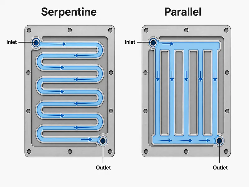
Five cold-plate variables decide IGBT junction temperature: flow rate, channel geometry, pressure drop, material, and the module interface. Flow rate and channel geometry set the heat-transfer coefficient. Raising flow or using finer channels increases wetted area and turbulence, which lowers thermal resistance but also raises pressure drop and pump power, so the design balances cooling against parasitic energy. Industry and manufacturer studies report that a specific direct-liquid-cooling structure — a microchannel cold plate bonded close to the module substrate — can cut thermal resistance by roughly 30% relative to a conventional configuration. The gain depends on the interface and the channel layout. Channel pattern matters too: serpentine paths favor even temperature at higher pressure drop, while parallel paths cut pressure drop but need careful distribution so downstream channels are not starved.
The interface is the variable most often underestimated. Baseplate flatness, mounting pressure, and the thermal interface material between module and cold plate govern contact resistance, and a poor interface can waste the gains a good channel design earned. This is where a matched liquid cold plate and thermal interface material help: the plate handles bulk heat removal while the interface layer absorbs flatness and assembly tolerance. Specify the cold plate design and the interface together, then validate with CFD and a bench measurement so a nominal thermal-resistance target becomes a repeatable one on the line.
Conclusion
Liquid cooling an IGBT is a budgeting exercise along the junction-to-coolant path, not a single clever component. Start from the duty cycle: fix the worst-case loss and the case temperature you must hold to protect the junction limit. Size the heat-removal side next — coolant, flow, and channel design — then treat the module-to-plate interface as a first-class variable, because contact resistance can quietly undo a strong cold-plate design.
Validation has to close on the junction, not only the case. Measure case temperature, then use the device datasheet’s junction-to-case and transient thermal impedance to estimate or measure the junction at worst-case loss. Also check flow rate, inlet temperature, pressure drop, temperature uniformity, and abnormal operating conditions; the applicable limits come from the target module’s datasheet. For this heat path, Trumonytechs’ relevant product families are liquid cold plates and thermal interface materials, matched to the module footprint and the interface that set contact resistance.
FAQ
Is liquid cooling compatible with all IGBT models?
Liquid cooling adapts to most IGBT modules, but the cold-plate design has to match the module’s footprint, baseplate, and power rating. A low-power module in a mild ambient may not need it, while a high-frequency traction module can require a microchannel plate and a tuned interface. Confirm the baseplate dimensions, mounting pattern, and target case temperature before assuming a standard plate fits.
How do I choose a coolant for an IGBT cold plate?
Coolant choice follows the environment and the loop materials, not thermal conductivity alone. Plain water cools well where freezing is not a risk and metals are protected; a water-glycol blend buys freeze protection at higher pumping demand; engineered dielectric fluids suit non-conductive or fire-sensitive designs at higher cost. Verify the fluid against the coldest and hottest expected conditions.
What flow rate and pressure drop should an IGBT cold plate target?
Flow rate and pressure drop follow from the thermal target, not from a fixed rule. Enough flow has to hold the case temperature under its limit at worst-case loss, while pressure drop stays low enough that pump power and seal stress remain reasonable. Confirm the balance with CFD and a bench test for the specific design.
Why does an IGBT run hot even with a cold plate installed?
A hot IGBT despite a cold plate has several possible causes, and the interface is a common one. Work through them in a testable order: coolant flow rate and inlet temperature, the contact interface (flatness, mounting pressure, interface material), trapped air or channel blockage, the actual heat load, and sensor calibration. Do not rule out the cold-plate side until flow and interface check out.
Further Reading
- Thermal Performance Optimization of Integrated Microchannel Cooling Plate for IGBT Power Module (Micromachines, 2023) — peer-reviewed study on how microchannel geometry drives IGBT junction temperature; supports the cold-plate design variables discussed above.
- Transient Heat Transfer in a Mini-Channel Flat-Plate Heat Sink for High-Heat-Flux IGBT (Micromachines, 2022) — peer-reviewed data on heat-flux capacity and case-temperature targets for liquid-cooled IGBTs.
- Design and Analysis of the IGBT Heat Dissipation Structure (Entropy, 2020) — peer-reviewed analysis of an IGBT heat-dissipation structure and thermal-resistance decomposition, useful for reading the junction-to-coolant path.
Related Articles
- The Role of Innovative Liquid Cooling Technology in Enhancing EV Range — how liquid cooling protects battery temperature to extend EV driving range.
- Integration And Optimisation Of Intelligent Cooling Systems — how to integrate and tune a liquid cooling system across a full thermal design.
- Revolutionizing Data Center Efficiency with Trumonytechs’ Liquid Cooling — liquid cooling applied to high-heat-density data-center hardware.
- Basic Principle of Liquid Cooling Plate — the working principle of the cold plate at the center of any liquid cooling loop.
