
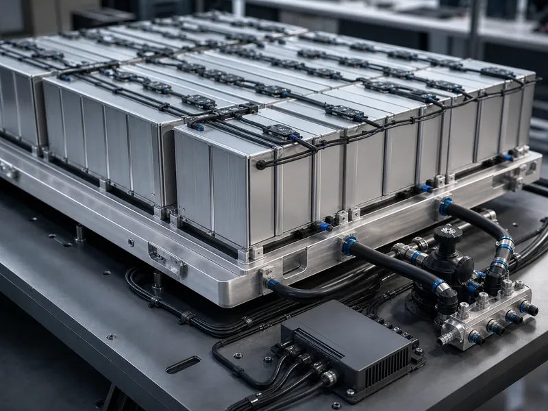
An intelligent cooling system for an EV or ESS battery pack combines three things: a liquid cooling path, the thermal interface between the cells and that path, and a sensing-and-control layer that keeps every cell inside a narrow temperature band. Optimising it is a trade-off across a few measurable variables: the target temperature window, the cell-to-cell temperature difference, coolant pressure drop, and the cell-to-plate interface. No single cooling technology is automatically “best”; the pack decides which one fits. This guide is written for pack thermal and product engineers deciding how to combine cells, interface materials, and cold plates. It does not cover pack electrical design, cell chemistry selection, or BMS safety-firmware development.
What Intelligent Cooling Integrates in an EV/ESS Battery Pack
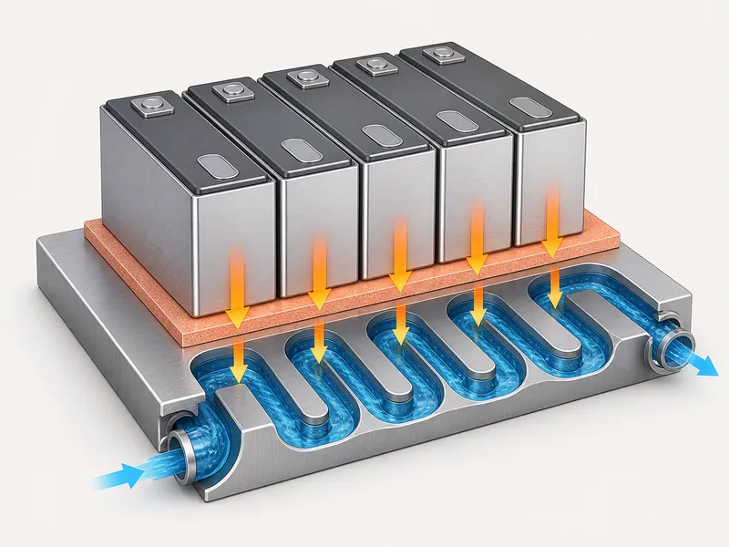
Intelligent cooling controls two things at once: where heat leaves the cells, and how evenly it leaves them, not only the coolant temperature. Heat generated inside each cell has to cross the cell wall, pass through a thermal interface material, enter the cold plate, and move into the coolant. That chain is the cell-to-coolant path, and every optimisation decision acts somewhere along it.
The temperature window is the first design constraint. Lithium-ion cells generally run best in a fairly narrow band, commonly cited around 15–35 °C, with best performance near 20–25 °C. Sustained operation above that band tends to accelerate degradation, and low temperatures cut usable capacity. Charging at low temperature may be restricted, derated, or gated behind preheating, depending on the cell chemistry and its datasheet limits. Treat these figures as typical engineering targets, and confirm the exact limits against the specific cell datasheet before fixing a control set point.
Temperature uniformity matters as much as the absolute value. Cells held at different temperatures age at different rates, and a persistently hotter cell can become the factor that limits usable pack life, so designs usually hold inter-cell temperature difference to a single-digit target, often under about 5 °C. EV and ESS packs reach that target differently because their duty cycles and packaging diverge, which is why their battery thermal management strategies are rarely interchangeable. The working loop is straightforward: the temperature window is the variable, drift out of band drives degradation and safety risk, and distributed sensing with controlled coolant flow is how you hold and verify it.
Choosing the Cooling Path: Where Liquid Cold Plates Fit
Pick the cooling path from the pack’s duty, not from a default. Heat load, cell and pack geometry, allowable pressure drop, sealing, weight, serviceability, and any propagation requirement decide whether a liquid cold plate, air, immersion, or a phase-change add-on fits. Liquid convection removes heat at a much higher rate than air for the same contact area, which is why indirect cold plates suit dense, high-heat-load packs. The alternatives earn their place when a specific constraint demands them.
| Cooling path | Heat removal | Uniformity control | Integration notes | Fits when |
|---|---|---|---|---|
| Air | Low | Hard at high density | Simplest, lightest | Heat load and density are low |
| Liquid cold plate | High | Good with channel design | Needs interface material and sealing | Heat load and density are high |
| Immersion | Very high | High across the pack | Adds sealing, weight, service constraints | High C-rate, or propagation must be slowed |
| PCM / heat pipe | Passive buffer | Local | Usually a composite add-on | Peak shaving or local hotspots |
The choice tracks the pack. Cell format and pack geometry decide where a plate can physically contact the cells or modules; heat load and the uniformity target then set channel layout and flow. Immersion adds resistance to runaway propagation, but it changes sealing, weight, and field service, so it tends to appear where discharge rates are high or propagation must be contained. Where a plate is the right answer, matched liquid cooling plates carry the heat away, and the interface material governs how efficiently that heat crosses into them.
The Sensing-and-Control Layer That Makes Cooling Intelligent
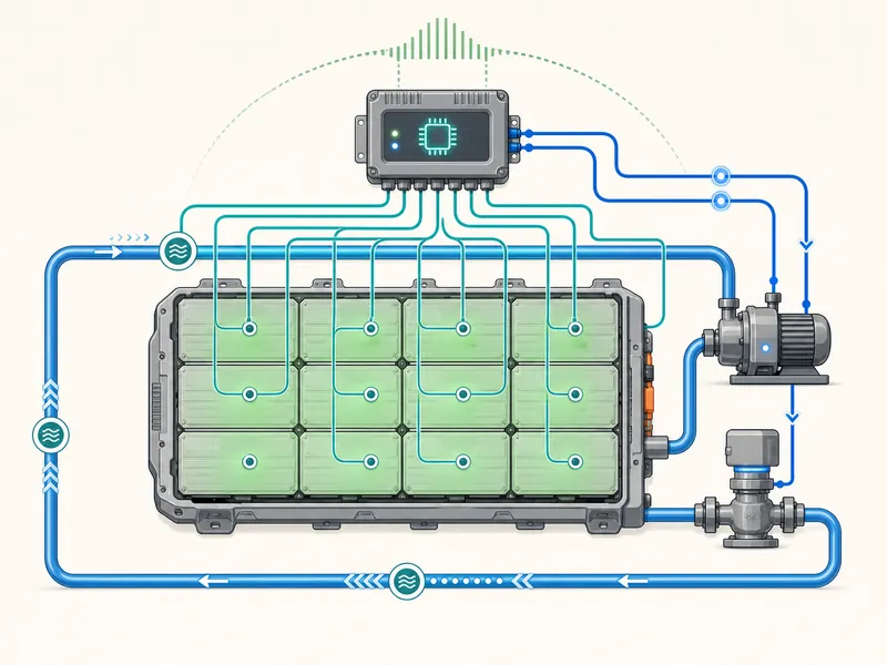
What makes a system intelligent is the closed loop: it reads distributed pack conditions and adjusts coolant delivery before temperatures drift, instead of running the pump at a fixed rate. That loop is what separates an intelligent system from a plate with a pump bolted to it.
Sensing supplies the inputs: cell or module temperatures, pack current and voltage, state of charge, ambient conditions, and often coolant inlet and outlet temperatures. Where physical probes are impractical, virtual sensing estimates cell temperature from a model. Sensor placement is itself a design variable. Too few points, and a hotspot can form between them unseen, so placement should be checked against the pack’s thermal model and its worst-case cell, not spread evenly for convenience.
Control strategies span simple temperature thresholds up to model predictive control, which forecasts thermal state from the upcoming load and trims flow or valve position before the heat arrives. The same layer can precondition a pack ahead of fast charging or a cold start. Matching cooling effort to the real load can lower parasitic pump and compressor energy compared with always-on cooling, though the saving depends on duty cycle and pack design and is not a fixed figure. The engineering test stays the same: sensing density is the variable, it decides whether the controller can even see a forming hotspot, and its adequacy is validated against the worst-case cell, not the average.
Optimisation Variables When Integrating Cells, Interface Materials, and Cold Plates
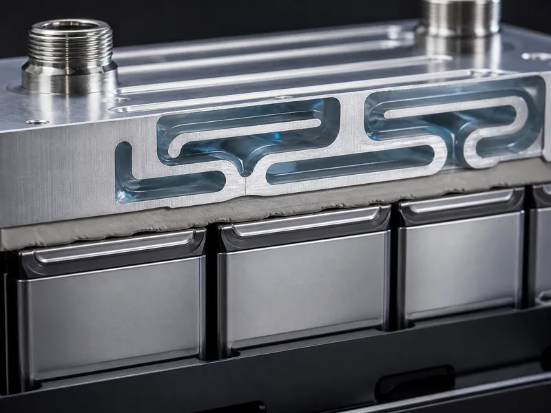
Four coupled variables set the outcome: heat load, temperature difference, pressure drop, and the cell-to-plate interface. Move one, and the others respond. Integration, not component selection in isolation, is where packs are won or lost.
Heat load and C-rate set the required coolant flow and the plate’s channel design. The temperature-difference target then drives the channel layout: counterflow and split-flow paths exist mainly to flatten the inlet-to-outlet gradient that a single straight channel leaves behind. Pressure drop is the standing tension against uniformity, because more flow evens temperatures but costs pump power; cold-plate channel geometry is chosen to hold the uniformity target at an acceptable pumping penalty, not at any flow rate.
The cell-to-plate interface is set by three things: the gap between cell or module and plate, the flatness of both surfaces, and the assembly stress the joint can tolerate. Those three decide which thermal interface material fits (a gap filler, a pad, or a structural adhesive) and whether it must also bond or electrically insulate. This is the point on the cell-to-coolant path where Trumonytechs‘ cold plates and thermal interface materials do their work: the plate removes heat, and the interface material controls how efficiently heat crosses into it. Select that material by its stated thermal conductivity, insulation status, curing behaviour, and structural strength. Use the value from the specific model’s datasheet; never infer a specification from a model number, and never generalise one model’s figure across a series.
Integration Challenges Across Real Duty Cycles
Transient duty is where packs actually fail: fast charging, cold starts, and single-cell faults can overwhelm a system that was tuned for steady state. Steady-state margin says little about the minutes that stress a pack hardest.
Fast charging spikes the heat load, so the control layer has to raise flow or pre-cool ahead of the session. When uniformity slips while cells are cold, near full charge, or being charged hard, that combination can raise the risk of hotspots and lithium plating; the plating risk is tied to those low-temperature and high-rate conditions, not to temperature spread on its own. Cold climates invert the problem. Usable capacity falls, and low-temperature charging may be limited, derated, or gated behind preheating, so the same loop has to warm the pack before it will accept current.
Thermal-runaway containment is a third axis. Better cooling can reduce the chance of initiation and, with immersion or inter-cell barriers, slow propagation, but cooling is one layer among several; it does not replace cell selection, barriers, and suppression when you prevent thermal runaway at pack level. Complexity carries its own risk. Modular cold plates ease integration into different module layouts, yet every added sensor, valve, and pump is another failure point, so an intelligent system should be validated for maintainability, not only for peak thermal performance. This guide does not size fire suppression or specify BMS safety logic; those belong to their own system reviews.
Conclusion
An intelligent cooling system is optimised from the passive path outward, not from the controller inward. Fix the temperature window and the uniformity target for your specific cells first, then let cell format, pack geometry, and heat load drive the cold-plate architecture and the interface material. The sensing-and-control layer optimises within those limits; it cannot rescue a plate or a thermal interface material that was mismatched to the pack. The distinction worth holding onto is that “intelligent” is not the sensors themselves but the closed loop that acts before temperatures drift, and it pays back only once the cell-to-coolant path beneath it is already sound. For engineers weighing that path, Trumonytechs supplies matched cold plates and thermal interface materials for the heat-transfer side of the decision.
FAQ
What temperature range should an EV or ESS battery pack stay in?
Most lithium-ion packs are held in a narrow band, commonly cited near 15–35 °C, with best performance around 20–25 °C. Sustained over-temperature tends to accelerate degradation, and low-temperature charging may be limited or require preheating depending on the cell chemistry, so treat these figures as typical targets and confirm the exact limits on the cell datasheet.
Cold plate or immersion cooling for a battery pack?
A liquid cold plate fits packs where heat load and density are high and indirect cooling is sufficient. Immersion earns its added sealing, weight, and serviceability cost mainly at high C-rates, or where slowing thermal-runaway propagation is a hard requirement.
How is cell-to-cell temperature difference kept low?
Even cell temperature comes from channel design and coolant flow that limit the inlet-to-outlet gradient, usually toward a single-digit target. Verification needs distributed sensing across the pack, not a single probe, because one sensor cannot see the spread between cells.
Does intelligent control save energy during fast charging?
Matching cooling effort to the real load can lower parasitic pump and compressor energy compared with always-on cooling. The saving depends on duty cycle and pack design, so it should be treated as duty-cycle-dependent rather than a fixed percentage.
What fails first when a cold plate and interface material are mismatched?
A poor cell-to-plate interface tends to show up as hotspots and a widening temperature spread. Heat cannot cross efficiently into the plate when the gap, flatness, or interface material is wrong, so the coolant loop cannot compensate no matter how hard it is driven.
Further Reading
- Neural Concept — The Impact of Efficient EV Battery Thermal Management — Engineering technical resource; supports the operating-window and temperature-uniformity points in this article.
- greyb — Liquid Cooled Systems for Thermal Management — Patent and engineering research aggregation; supports the cold-plate versus immersion architecture comparison.
Related Articles
- The Role of Innovative Liquid Cooling Technology in Enhancing EV Range — Shows how liquid cooling and tighter battery temperature control translate into usable EV range.
- Basic Principle of Liquid Cooling Plate — Explains how a liquid cooling plate moves heat in a closed loop, the layer beneath most of this article.
- Difference Between Heat Sink and Cold Plate — Helps decide between air-side heat sinks and liquid cold plates when thermal budget and space are tight.
- What is a Battery Cold Plate? — Introduces the battery cold plate as the core component that removes heat from cells by contact.
- Comprehensive Comparison of Liquid Cooling Plates vs. Traditional Cooling Technologie — Compares liquid cold plates against air cooling for high-density EV and storage packs.
