
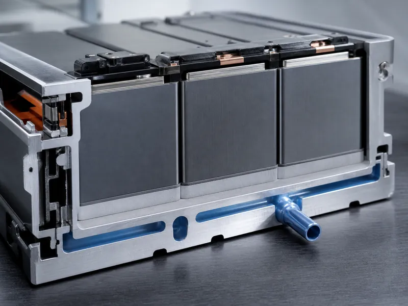
Silicone-free thermal interface materials earn their place in a battery pack wherever silicone bleed or outgassing would put the cell-to-coolant heat path at risk. For a pack thermal engineer the question is narrow. Does this assembly hold surfaces, sensors, or bonded joints that silicone contamination can degrade? And can a silicone-free chemistry keep thermal conductivity across the gaps and aging the module will see? This article covers what has actually advanced in silicone-free thermal interface materials, how they compare with silicone types on the variables that drive selection, and where they fit in a liquid-cooled EV or energy-storage pack.
Why Silicone Bleed and Outgassing Threaten the Battery Heat Path
The recurring failure mode with silicone thermal interface materials is migration. Low-molecular-weight siloxanes can volatilize or bleed under heat, compression, and low pressure, then redeposit on nearby surfaces. In a battery module the heat path runs from the cell wall through the interface material to a cold plate. Oil that creeps onto a cold-plate sealing face, a sensor lens, or a printed circuit board can then lower surface resistance and breakdown voltage or interfere with later bonding and cleaning. Several material sources describe the same mechanism, which makes it a design constraint to plan around in silicone-sensitive assemblies.
Contamination control is the practical reason a line may specify silicone-free chemistry. Where silicone-based and silicone-free processes share tooling, bled siloxane can foul solder joints and adhesive bonds on unrelated parts. A team may then choose silicone-free, low-VOC formulations when downstream bonding or cleanliness rules are tight. The driver is process cleanliness and repairability. Claims that silicone is toxic at a fixed parts-per-million limit are not supported here and should be checked against a standards body before they are repeated.
Silicone still suits most general electronics, so the choice is scenario-based. When a module has no exposed optics, no bleed-sensitive sensors, and no downstream bonding that stray oil would spoil, conventional silicone materials such as a thermally conductive silicone grease or silicone pad remain reasonable. The case for going silicone-free grows as an assembly adds contamination-sensitive surfaces or stricter cleanliness rules.
What “Silicone-Free” Changes in TIM Chemistry
“Silicone-free” describes the matrix, not the filler, so the heat-carrying part of the material is largely unchanged. These systems replace the polysiloxane backbone with acrylic, polyurethane, or silyl-modified polymer chemistries. Thermal conductivity still comes from ceramic or metallic fillers dispersed in that matrix. Dropping silicone therefore does not by itself raise or lower conductivity; the filler chemistry and loading do.
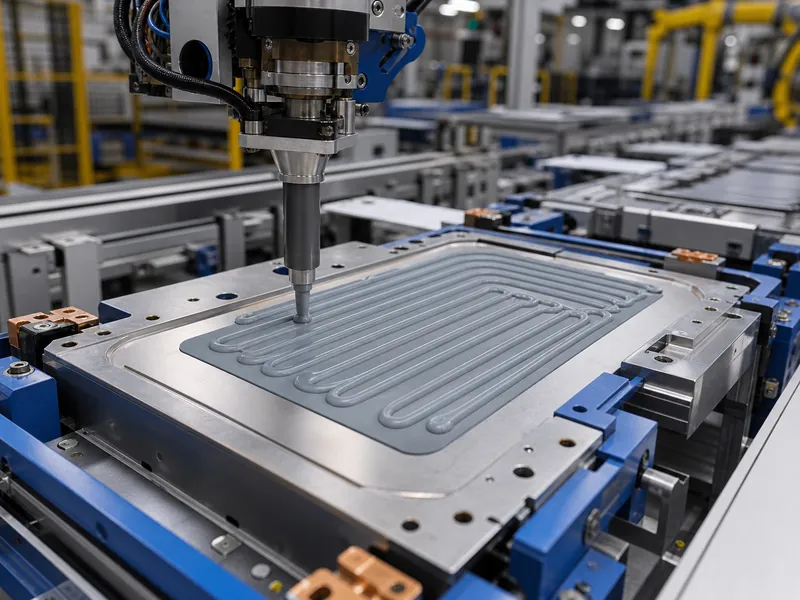
Format options largely mirror the silicone lineup, which keeps assembly methods familiar. Silicone-free chemistries come as gap fillers, gap pads, thermally conductive adhesives, and greases. A team can usually match an existing process, whether that means dispensing a form-in-place filler or placing die-cut thermal pads. Curing behavior shifts with chemistry: some silicone-free systems are non-curing and allow immediate power-up, while reactive two-part adhesives trade open time for structural bonding strength.
Research-stage chemistries aim to push conductivity by engineering the filler network. Systems under study include oriented ceramic or carbon pathways, poly(ionic liquid) matrices being explored for interfacial adhesion, and liquid thermal interface materials that combine liquid metal with solid particles to hold a conductive network together. These are directions to watch, not settled specifications. Treat any single reported conductivity or modulus figure as unconfirmed until a datasheet and a second source support it.
Silicone-Free vs Silicone TIMs: Trade-offs to Verify
Silicone-free grades tend to help with contamination and dielectric behavior but can give up long-term compliance, and each tendency needs grade-level verification. The table lists typical tendencies and risks to check on a datasheet, not fixed properties of the material family. The value in any cell depends on the exact grade and its test conditions.
| Variable | Silicone-based (typical) | Silicone-free (typical, verify by grade) |
|---|---|---|
| Contamination / outgassing | Siloxane bleed and migration under heat and compression | Lower bleed where siloxane migration is the controlling risk |
| Dielectric behavior | Adequate; can shift with aging | Better insulation reported for some tested grades |
| Behavior after high-temperature aging | Often stays viscoelastic | Some tested grades harden or embrittle |
| Thermal conductivity | Set by filler, not matrix | Set by filler, not matrix |
| Temperature range | Broad, chemistry-dependent | Grade-dependent; confirm on datasheet |

Aging behavior is the trade-off most often misstated, so it needs a verification path. In a 2,000-hour high-temperature storage aging exposure at 125 °C run to JEDEC JESD22-A103E and published in the journal *Materials*, a silicone-free gap filler hardened while the silicone-based material stayed viscoelastic. The silicone-free sample also showed better dielectric behavior for insulation-critical use. That result covers the two grades tested under that storage-aging condition. It does not extend to every silicone-free product or to high-low thermal cycling. The practical step is to qualify aged hardness and bond-line behavior for the specific grade, not to assume they hold.
Conductivity comparisons carry the biggest myth, and it is worth correcting directly. Because gap pad thermal conductivity follows filler type and loading, a silicone-free grade is not inherently higher- or lower-conducting than a silicone one. Either can be formulated across a wide range. Any claim that silicone-free materials automatically outperform silicone grease or pads should be read as grade-specific.
Matching a Silicone-Free TIM to the Cell-to-Coolant Path
Selecting a silicone-free TIM for a pack starts with gap, because gap decides the material class. Match the interface gap and surface flatness between the cell or module and the cold plate to the material’s compliance. Wide, uneven gaps favor a conformable gap filler that fills voids under low pressure, while thin, flat interfaces can take a thinner pad or a dispensed film. A mismatch here shows up as trapped air and hot spots, so confirm the worst-case stack-up gap before fixing a format.
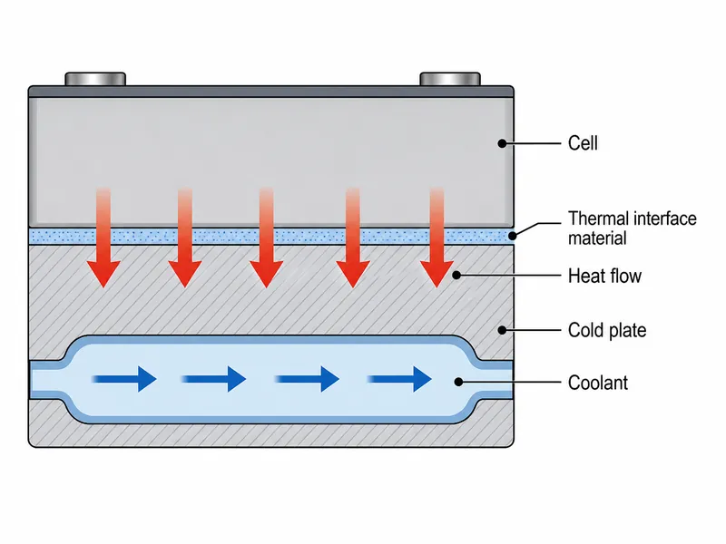
Assembly stress and automation shape the format as much as the thermal numbers. A low-modulus silicone-free filler that compresses to a minimal bond line without loading delicate cells can be worth more than a marginally higher conductivity that needs high clamp force. A dispensable form-in-place material also suits automated pack lines better than hand-placed pads. Where the interface also carries structural load, a silicone-free thermally conductive adhesive moves the decision toward bond strength and cure schedule, which then constrains takt time.
Curing, serviceability, and insulation close out the selection, and they tie back to pack lifecycle goals. A non-curing filler lets a line power-test immediately. A reactive adhesive locks in position but complicates rework and end-of-life disassembly, a constraint that matters as packs are designed for battery safety and liquid cooling, serviceability, and recycling. Because most pack interfaces must also electrically isolate the cell from the cold plate, confirm dielectric strength at the aged, compressed bond line, using the mechanical, geometric, and dielectric tests appropriate to each property. An aging exposure such as JEDEC JESD22-A103E sets the storage condition before and after which those separate tests are run. On its own it does not measure hardness, bond-line thickness, or dielectric strength. Checking these four variables together keeps a silicone-free choice sound across the module’s life.
Where Silicone-Free TIMs Fit
Silicone-free chemistry fits where cleanliness rules and manufacturing constraints already point away from silicone. EV and energy-storage packs are one such case. When a design targets cell temperatures near room temperature and treats sustained excursions toward the upper cell limits as a life and safety risk, the interface material has to hold up under thermal cycling without fouling cold plates, sensors, or bonded joints. Battery energy-storage systems face the same drivers at larger scale, so silicone-free gap fillers and adhesives are a common option in pack thermal designs.
Beyond batteries, the same pull holds in any silicone-sensitive assembly. Optical, sensor, medical, and aerospace hardware can be intolerant of bleed or outgassing, so silicone-free materials serve those uses for the contamination reason that applies inside a pack. The engineering logic carries over even though temperature and gap constraints differ by application.
On the materials-science side, near-term progress is incremental and filler-driven. Nanofiller reinforcement, oriented conductive pathways, and liquid-metal hybrids each aim to lift conductivity while holding compliance, and each still faces the same qualification bar around aging, insulation, and manufacturability. Tracking that qualification data is a more reliable gauge of progress than headline conductivity numbers.
Conclusion
The core judgment for silicone-free thermal interface materials is that they are a contamination and cleanliness decision first and a conductivity decision second. Specify them when a pack has silicone-sensitive surfaces, tight manufacturing rules, or serviceability and insulation needs that silicone bleed would undermine, and stay with silicone where none of those pressures exist. The property most often misread is aging. Because some silicone-free grades harden over time, qualify aged hardness, bond-line thickness, and dielectric strength for the specific grade. Use a recognized storage-aging exposure such as JEDEC JESD22-A103E as the condition, and the appropriate mechanical and dielectric tests for the measurements. Matching the material to gap, assembly stress, curing, and insulation across that heat path is where Trumonytechs’ interface materials and cold-plate designs are meant to work together.
FAQ
Do I need a silicone-free gap filler for an EV battery pack, or is silicone acceptable?
Contamination sensitivity decides this, not the battery itself. Specify a silicone-free filler when the pack has bleed-sensitive sensors, sealing faces, or bonded joints, or when the line enforces silicone-free, low-VOC rules. Where none of those apply, a well-chosen silicone material can still perform.
Does a silicone-free TIM lose thermal conductivity or get brittle after thermal aging?
Some grades harden with age, so this must be verified for the specific product. A published 2,000-hour, 125 °C high-temperature storage aging study to JEDEC JESD22-A103E found a silicone-free gap filler hardened while a silicone one stayed viscoelastic. That is why aged mechanical and dielectric behavior should be qualified grade by grade.
Can silicone outgassing contaminate the cold plate, cells, or PCB in a module?
Yes, and that risk is the main reason silicone-free materials exist. Low-molecular-weight siloxanes can migrate under heat and compression onto sealing faces, sensors, or boards, lowering surface resistance and breakdown voltage or spoiling later bonding and cleaning.
Are silicone-free TIMs always higher conducting than silicone ones?
No; conductivity follows filler type and loading, not whether the matrix is silicone-free. Either chemistry can be formulated across a wide conductivity range, so compare grade to grade instead of by material family.
Further Reading
- A Comparative Study of Thermal Aging Effect on Silicone-Based and Silicone-Free Thermal Gap Filler Materials (journal *Materials*, 2021) — Peer-reviewed high-temperature storage aging study (JEDEC JESD22-A103E) supporting the hardening and dielectric trade-offs above; applies to the two tested grades, not all silicone-free materials.
Related Articles
- Ceramic Thermal Paste: What It Is, How It Works, and When to Use It — Explains how a ceramic-filled paste works and when it fits, useful when weighing filler options for an interface.
- Conductive vs Non-Conductive Thermal Paste: A Selection Guide — Helps decide when a cell-to-cold-plate interface must stay electrically isolated.
- Phase Change Thermal Pad: Transition Band, Clamp Pressure, and Bond Line — Covers phase-change pads and the clamp-pressure and bond-line variables that govern them.
- Thermal Interface Materials Types & Characteristics — Maps the main TIM classes and where each one fits in a thermal path.
- Thermal Paste Alternative: Engineered Options and How to Choose — Reviews engineered alternatives to paste and how to choose between them.