
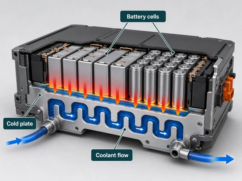
Battery safety in electric vehicles (EVs) and energy storage systems (ESS) turns on the hottest cell and the temperature spread between cells. Lithium-ion cells lose life quickly above their design window, and once local heat outruns dissipation they can enter thermal runaway. A thermal system’s real job is therefore to hold every cell inside a narrow band. Battery thermal-management literature widely reports a working target near 15–45 °C for cell temperature, with a cell-to-cell spread held under about 5 °C. Liquid cooling has become the common way to meet both targets in high-power packs. The changes worth tracking sit less in the coolant itself and more in how heat is routed from the cell into that coolant. This article covers indirect and direct cooling, cold-plate and channel design, phase-change materials as a buffer, and where the approach still costs more than it returns. It does not cover coolant chemistry qualification or high-voltage isolation design.
Why Battery Temperature Limits Define Pack Safety
Safety margin in a lithium-ion pack is governed by the hottest cell and the spread between cells. A low pack-average reading can therefore hide a cell sitting near its limit. A cell held near the top of its window ages faster and moves closer to exothermic breakdown. When the pack is uneven, one cell can reach that onset while the average still looks normal. That is why engineers instrument several cells across a module and treat a low average as an incomplete signal. Preventing overheating is as much a uniformity problem as a heat-removal one, and that framing is the core reason effective thermal management matters for pack safety.
For stationary storage, the safety case also has to account for a cell that does fail. Under UL 9540A, the North American test method for thermal-runaway fire propagation in battery ESS, a system is evaluated for how a single-cell event spreads to neighbors. The test also measures how much heat and gas the module releases. As an engineering view, not a UL requirement, reading a cooling architecture through that lens adds a propagation question: whether the design routes cell heat into a controlled path instead of letting cells heat each other.
The Role of Liquid Cooling in Battery Safety
Liquid cooling controls cell temperature faster and more evenly than air because a liquid carries far more heat for the same mass. Water’s specific heat capacity sits near 4.18 kJ/kg·K against roughly 1.0 kJ/kg·K for air. A modest coolant flow can therefore absorb a charge or discharge spike that forced air would smear across the pack. How much of that spike actually clears depends on flow rate, heat-exchange area, and loop design, not on the coolant’s heat capacity alone. The cost is added mass, sealing, and a pump to drive, so liquid cooling suits packs whose thermal load justifies it.
Indirect vs Direct Liquid Cooling
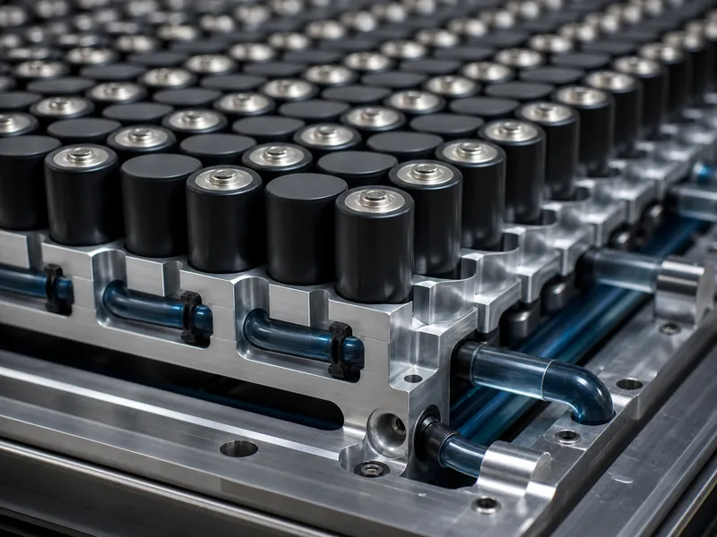
The first architecture choice is whether coolant touches the cells, and it hinges on the coolant’s electrical properties. Indirect cooling keeps coolant inside cold plates, tubes, or jackets, so a water-glycol mix works because it never meets live terminals. That coolant choice still has to weigh freeze point, corrosion, and material compatibility with the loop. Direct, or immersion, cooling submerges the cells in a validated dielectric fluid to remove the cell-to-plate thermal resistance. That improves uniformity while adding fluid cost, sealing, and maintenance. Plain water suits neither an immersion design nor a cell-adjacent leak path, because its conductivity would short cells.
In an indirect design the cell-to-plate interface often carries the limiting thermal resistance, so gap-filler choice, surface flatness, and assembly stress can move pack temperature as much as flow rate does. When uniformity misses target, the interface is a practical first place to check. Direct cooling removes that interface but adds a fluid-compatibility and maintenance task in its place. Which path fits depends on the duty cycle, packaging, and serviceability a program can accept. Many EV packs use indirect cold-plate cooling for reliability and fit, while immersion appears more in high-discharge and specialized ESS cases.
Cold-Plate and Channel Design Choices That Move Heat
Channel and cold-plate geometry is where much of liquid cooling’s engineering headroom sits. Channel layout, cross-section, and how flow splits across the plate set both temperature uniformity and the pressure drop the pump must overcome. The two work against each other: geometry that lowers cell temperature tends to raise pumping load. A workable cold-plate design therefore trades uniformity against parasitic power for the specific duty point. The verification step is concrete: map the temperature spread across the plate at the worst-case load, then confirm the pressure drop still fits the pump curve.
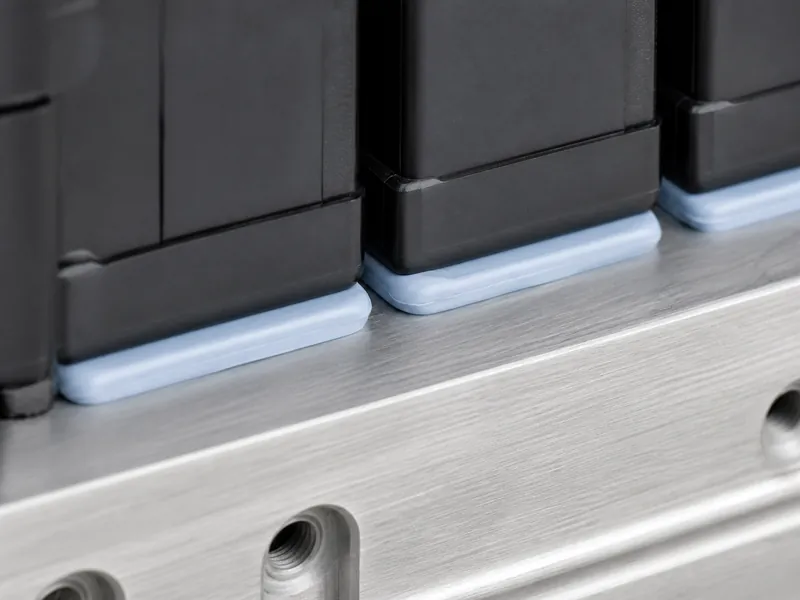
The plate-to-cell interface deserves equal attention because it carries every watt the plate removes. A thermal interface material fills the microscopic gaps between cell and plate. Its conductivity, thickness, and tolerance to assembly variation govern how much of the plate’s capacity reaches the cell. Choosing that material by gap, curing behavior, and bonding need belongs inside the cooling decision, not after it.
PCM as a Thermal Buffer in Liquid-Cooled Packs
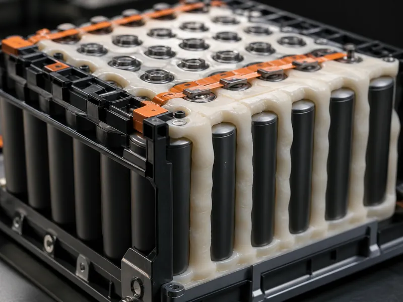
Phase-change materials (PCM) add time to a thermal spike by absorbing heat at a near-constant temperature as they melt. Placed between cells, a PCM takes up latent heat when load surges and gives it back later, smoothing short peaks that would otherwise push the liquid loop to its limit. Because PCM on its own conducts heat poorly and eventually saturates, it pairs with an active loop instead of replacing one. Some hybrid PCM-and-liquid designs report lower pump duty, since the PCM handles transients while the loop handles steady load. The size of that benefit depends on the design and duty cycle, and it should be verified for the application.
Liquid Cooling in Production EVs and ESS

Pack-level liquid cooling reached mainstream EV programs before it was standard, and production use is what proved it at scale. Early high-volume EVs circulated coolant through the pack to hold cell temperature during charging and sustained load. Comparable indirect loops later became common across high-energy EVs and grid-scale ESS. The pattern matters more than any single model. Once packs pushed past a certain power and energy density, air cooling struggled to hold the cell-to-cell spread, and liquid loops became the practical baseline for performance and safety in that class.
How Trumonytechs Approaches Pack Cooling
Trumonytechs works at the cell-to-coolant heat path, supplying liquid cold plates and thermal interface materials that sit between the cells and the loop. Those are the two product families the company offers for that path. As a general engineering point, not a claimed performance result, the plate and interface act together. Matching plate geometry to the cell format, and choosing an interface material for the actual gap and assembly method, works on the interface that usually limits an indirect design. In practice the work is that matching: cold-plate architecture selected for cylindrical, prismatic, or pouch formats, and interface materials specified by gap, curing, and bonding need. Pack builders weighing these variables against a duty cycle can scope the plate and interface combination with our design team.
Cost, Complexity, and Integration Limits of Liquid Cooling
Liquid cooling earns its place where the thermal load justifies its cost, mass, and integration burden. A loop brings pumps, seals, coolant, and failure modes that air cooling avoids. Fitting one into a pack designed around a different method is often the hard part. The workable order is to size the system to the duty cycle: confirm the worst-case heat load and the required cell-to-cell spread, then choose the least complex architecture that meets them. For ESS, that sizing sits alongside propagation resistance, since preventing thermal runaway in a BESS is a system-level task the cooling path supports but does not settle alone.
Conclusion
The judgment to carry away is that liquid cooling’s real advances sit in the heat path, and pack safety is set by the cell-to-cell spread more than by the pack average. Choose the architecture by asking whether coolant must contact the cells, then treat the plate-to-cell interface as the variable that most often limits uniformity in an indirect design. PCM buffers transients but does not replace an active loop, and immersion buys uniformity at the price of fluid and maintenance work. The most common misread in real packs is tuning the average while ignoring the spread, which is the number that governs aging and safety margin.
FAQ
What makes liquid cooling more effective than air cooling for battery packs?
Liquid cooling holds a tighter cell-to-cell spread because a liquid carries far more heat for the same mass than air. With a specific heat near water’s, a coolant flow absorbs charge and discharge spikes that forced air would spread across the pack. How much clears depends on flow rate, heat-exchange area, and loop design. The cost is added mass, sealing, and a pump, so the method fits high-power packs.
What is the difference between indirect and direct liquid cooling?
The difference is whether coolant touches the cells, which is set by the coolant’s conductivity. Indirect cooling keeps a water-glycol coolant inside cold plates or tubes so it never meets terminals, while direct immersion submerges cells in a validated dielectric fluid to remove the cell-to-plate resistance. Indirect designs are common for reliability and packaging fit; immersion trades higher fluid and sealing cost for better uniformity.
What role do phase-change materials play in a liquid-cooled pack?
Phase-change materials act as a thermal buffer, taking up latent heat at a near-constant temperature during a spike. That smooths short transients so the active loop is not driven to its limit, and the stored heat releases later when load drops. Because PCM conducts heat poorly and eventually saturates, it supplements liquid cooling instead of replacing it.
Can a liquid cooling system be tailored to a specific EV or ESS pack?
Yes. The coolant, channel layout, cold-plate geometry, and interface material are all selected against the pack’s cell format and heat load. The variables that matter most are the cell-to-plate interface and the balance between temperature uniformity and pump pressure drop. Matching those to the duty cycle is what makes a system fit a particular pack.
Further Reading
- UL 9540A Test Method for Battery Energy Storage Systems — UL Solutions (standard). Defines how thermal-runaway fire propagation is evaluated in battery ESS at cell, module, and installation level; supports the propagation-resistance point for stationary storage.
- Advances and Challenges in the Battery Thermal Management Systems of Electric Vehicles — peer-reviewed review (PMC). Background on passive, active, and hybrid BTMS strategies and the temperature-uniformity targets referenced above.
Related Articles
- What Are The Best Materials To Seal EV Batteries? — Covers the sealing materials that keep moisture and contaminants out of a pack, a companion concern to keeping cells cool.
- EV Battery Module Types: Cylindrical, Prismatic, and Pouch Cell Formats Compared — Explains how cell format drives cold-plate design and interface-material choice, the variables this article treats as central.
- Cooling by Conduction Technology for Battery Packs — Goes deeper on the conduction path from cell to plate through water cooling plates and thermal interface materials.
- How Does Liquid Cooling Extend The ESS Lifespan? — Shows how holding temperature with a water-glycol loop translates into longer stationary-storage life.
- Optimising Battery Pack Thermal Management — A broader view of how temperature affects lithium-ion performance and which cooling solutions apply.
