
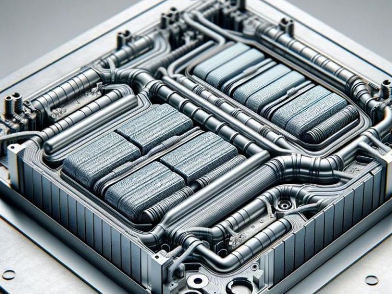
A battery cold plate is a liquid-cooled metal plate that sits in the heat path between battery cells and a circulating coolant, pulling heat out of the pack through direct contact. It is the conductive interface that a battery cold plate design turns into a controlled thermal boundary. Cells conduct heat into the plate, coolant carries it through internal channels to a remote heat exchanger, and the pack stays inside its usable temperature window. For engineers integrating cylindrical, prismatic, or pouch cells, the cold plate is where cell-level heat generation meets pack-level thermal management. Its geometry, flatness, and flow path set how much fast-charge or high-rate discharge the pack can sustain before it has to derate.
The scope here is the plate itself: what a battery cold plate does, how a liquid plate moves heat, which types suit which cell formats, and the material and interface variables that set performance. Coolant-loop sizing, chiller selection, and cell chemistry are separate decisions downstream of the plate and stay out of scope.
What a Battery Cold Plate Does in the Cell-to-Coolant Heat Path
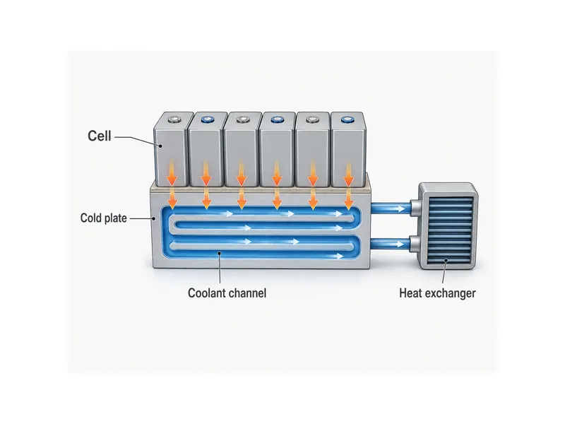
A battery cold plate gives every cell a defined conduction path to the coolant, replacing the uncontrolled route that plain air cooling leaves. Cells generate heat internally during charge and discharge, and without a low-resistance path out, that heat raises cell temperature and widens the spread between cells. A plate routes each cell’s heat to the coolant along a short, repeatable path, so the pack tracks its cooling system instead of ambient air.
Cold-plate cooling earns its place where heat density and duty cycle are high, such as EV traction packs and cycled energy-storage racks. Cells there are packed tightly and worked hard, so better heat extraction widens the usable power and charge window before cells reach their temperature limit. Liquid carries far more heat per unit volume than forced air, so water cooling plates for battery packs handle loads that would need large ducts and fans to match.
The cold plate is one layer of a larger battery thermal management system, not the whole of it. It handles the conductive extraction step; sensors, controls, pumps, and the heat exchanger handle sensing, flow, and rejection. Reading the plate as the conduction stage keeps its design tied to the variable it actually controls: the thermal resistance from cell surface to coolant.
How a Liquid Cold Plate Moves Heat Away from the Cells
A liquid cold plate moves heat in two linked steps: conduction from the cell through the plate wall, then convection into the coolant. Heat crosses the interface between cell and plate, spreads through the plate material, and is swept away by coolant in machined or formed channels. Each step adds thermal resistance, so plate performance is the sum of contact resistance, wall conduction, and coolant-side convection — not any single number.
Peak temperature and temperature uniformity both matter, and a plate has to control the two together. A common engineering target keeps cells near a 20–40 °C working window, though published ranges vary: some sources cite 20–35 °C, others run up to about 50 °C, so the window is worth verifying for the specific chemistry and duty cycle. Cell-to-cell differences are held more tightly. Two peer-reviewed liquid-cooling studies keep the spread under roughly 5 °C, because a wide spread ages some cells faster than others and drags down pack life and balance.
Coolant flow sets the convective side, and it trades against pumping cost. Raising the flow rate lowers coolant-side resistance and flattens the temperature rise along the channel, but it also raises pressure drop, which the pump has to pay for. Sound liquid cooling system design balances channel cross-section, path length, and flow so the plate holds its uniformity target without an unnecessary pressure penalty, then checks it against the pack’s real heat load.
Cold Plate Types and the Cell Formats They Suit
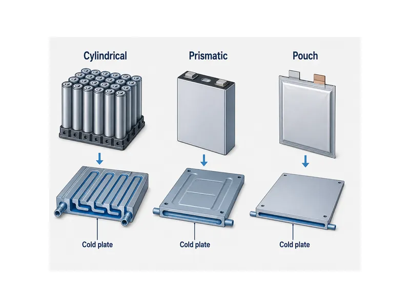
Cold plate types differ mainly in how the coolant channel is formed. That construction is what maps a plate to a cell format. The practical families are extruded plates, stamped-and-brazed plates, tube-in-plate (harp tube) assemblies, serpentine-channel plates, and microchannel plates. Choosing among the different types of cooling plates starts from cell geometry, contact area, and how much channel freedom the layout needs.
Prismatic and pouch cells present a large flat face, so they pair with flat plates carrying routed or stamped channels. Stamped-and-brazed and extruded plates give a broad, flat contact surface and let the channel pattern follow the module footprint, which suits the sandwich and bottom-cooled arrangements common with those formats. Flatness and channel coverage under the cell face decide contact quality here.
Cylindrical cells are cooled several ways — through bottom plates, side-wall contact, or serpentine channels that weave between rows — depending on how the module exposes the cell surface. Microchannel cold plates raise contact area and coolant-side heat transfer by splitting flow into many fine passages, which helps high-heat-flux layouts but raises pressure drop and tightens manufacturing tolerances. The trade holds across styles: finer, denser channels buy uniformity and heat transfer at the cost of pumping power and fabrication difficulty, so cell format and duty cycle drive the pick.
Materials, Flatness, and Flow: The Variables That Set Performance
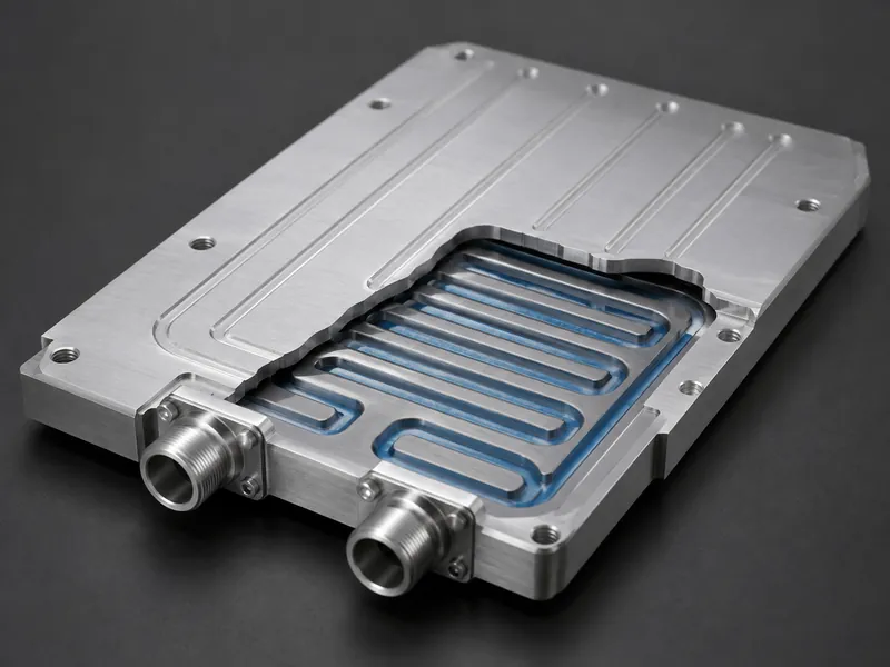
Material choice sets the conduction ceiling. It is a weight-versus-conductivity trade, not a search for a single best metal. Copper conducts heat at roughly 385–400 W/m·K, well over double the aluminum alloys used in plates, so copper appears where local heat flux is high. Aluminum alloys are common in EV and ESS plates because they are lighter and easier to form. The practical question is whether a given hot spot justifies copper’s added weight and cost.
Plate thickness and flatness govern the contact side of the resistance budget. Thickness balances heat spreading and structural strength against mass and pack volume. Flatness controls how evenly the plate meets the cell face: a plate that is out of flat leaves gaps no coolant flow can recover, because the heat never crosses into the plate. Flatness tolerance and surface finish are therefore specified as tightly as the thermal target.
Flow-path design closes the loop between heat load and pump budget. Channel cross-section, length, and layout set both how uniform the plate stays and how much pressure the coolant loses crossing it, and those two goals pull against each other. The task is to hold cell-to-cell uniformity across the worst-case heat load while keeping pressure drop within what the pump and coolant allow, then confirm it on the real duty cycle.
Interface Materials and Pack Integration
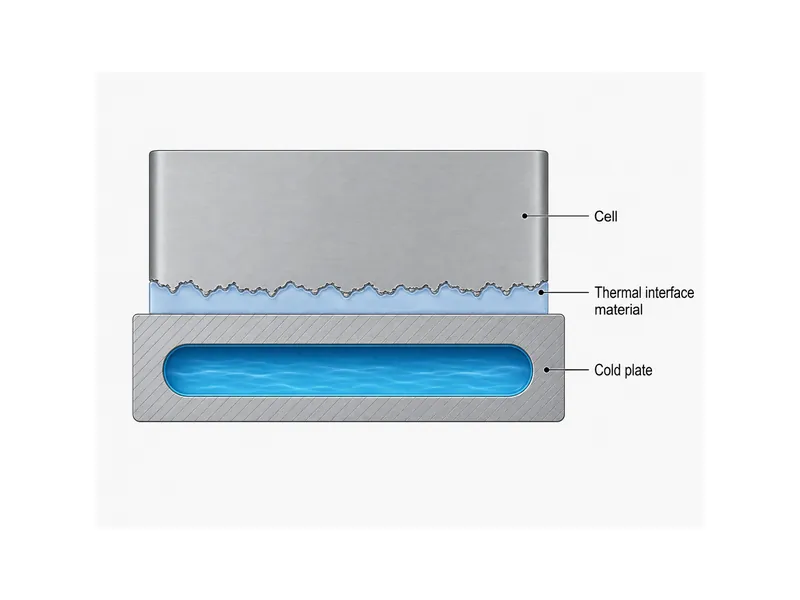
The interface between cell and plate is where an otherwise good cold plate wins or loses. Contact resistance can dominate the heat path, so the gap between cell and plate has to be managed as carefully as the plate itself. Cells and plates are never perfectly flat, so a thermal interface material fills the microscopic gaps and displaces insulating air. Selecting that material by gap thickness, assembly stress, curing behavior, and whether structural bonding is also needed is what turns the plate’s conduction potential into real heat extraction. A poorly matched gap filler can add significant resistance of its own.
Integration has to satisfy thermal, structural, and safety goals at once. The plate must sit flat against the cells under clamping load, tolerate vibration and thermal cycling, and route coolant without leak paths near live cells, since a coolant breach is a direct safety event. Well-managed contact also raises the margin against thermal runaway by keeping cells cooler and more uniform, which is why interface quality is treated as a safety variable, not only a performance one.
Trumonytechs works at this interface, supplying liquid cold plates and thermal interface materials specified together for a given cell format and pack layout. Matching the plate, the gap filler, and the structural bond against the same thermal and assembly targets keeps the interface from being sourced in isolation. Treating that interface material as a commodity gap filler is easy to underspecify in a first pack design.
Conclusion
A battery cold plate is best understood as the conduction stage of the pack’s heat path, and its value lives in the resistances it controls: contact at the cell, conduction through the wall, and convection into the coolant. Reading it that way points to what you actually specify — the cell-to-coolant thermal resistance, the peak cell temperature, the cell-to-cell temperature spread, and the pressure drop that holds them together — not a single headline figure. Cell format drives plate type, material choice is a weight-versus-conductivity trade, and flatness plus flow decide whether the plate holds uniformity under real load.
The point easiest to misread is that the plate alone does not guarantee cooling. Without a matched interface material and flat, leak-free integration, contact resistance can undo a well-designed plate, so specify the plate and its interface as one system. Engineers scoping a new pack can decide the plate architecture and interface material together, and Trumonytechs supports that step with matched cold plates and thermal interface materials for the target cell format.
FAQ
What temperature range should a battery cold plate keep cells in?
A common engineering target is roughly 20–40 °C, though published ranges vary: some sources cite 20–35 °C, others run up to about 50 °C. Treat it as a window to verify for your cells rather than a fixed limit. Cell-to-cell differences are held more tightly, under about 5 °C in liquid-cooling studies, and the plate should be sized for the worst-case heat load inside that band.
Do I need a liquid cold plate, or is air cooling enough?
Air cooling can be enough for low heat density and gentle duty cycles. A liquid cold plate becomes necessary once sustained heat load or a tight uniformity target exceeds what forced air can hold. The deciding variables are pack heat flux, how tightly cells are spaced, and the uniformity target; when any of those is demanding, liquid’s higher heat capacity is what keeps the spread in range.
Cold plate, immersion, or direct cooling — which suits my cell format?
Indirect cold-plate cooling is a common fit for prismatic, pouch, and cylindrical packs, because it keeps coolant separated from cells and matches a flat or channeled plate to the cell face. Immersion and direct-contact approaches can raise heat transfer further but add dielectric-fluid, sealing, and serviceability constraints. The choice follows cell format, safety requirements, and how much integration complexity the program will accept.
What coolant do battery cold plates use?
Battery cold plates commonly run a water–glycol mixture, which balances heat capacity against freeze protection for automotive and outdoor-storage duty. The exact mix and additives depend on the loop’s operating temperature range and corrosion requirements. Coolant selection is made together with the plate material and system, not in isolation.
Further Reading
- Optimization of a Lithium-Ion Battery Thermal Management System with CPCM/Liquid Cooling (Materials, 2022) — peer-reviewed study supporting the sub-5 °C cell-to-cell uniformity target used above.
- Multi-objective optimization of a microchannel liquid-cooled plate for a lithium battery pack (PLoS One, 2024) — peer-reviewed analysis of the uniformity-versus-pressure-drop trade behind channel design.
Related Articles
- Basic Principle of Liquid Cooling Plate — explains how a liquid cooling plate carries heat away, filling in the working mechanism behind this definition.
- The Role of Innovative Liquid Cooling Technology in Enhancing EV Range — shows why keeping EV cells in range with liquid cooling protects usable range.
- Difference Between Heat Sink and Cold Plate — clarifies how a cold plate differs from a heat sink for readers new to the terms.
- Integration And Optimisation Of Intelligent Cooling Systems — covers integrating a cold plate into a controlled pack cooling system.
- IGBT Cooling Using Liquid Technology: Enhancing Electronic Efficiency — extends the same liquid cold-plate idea to cooling power electronics.