
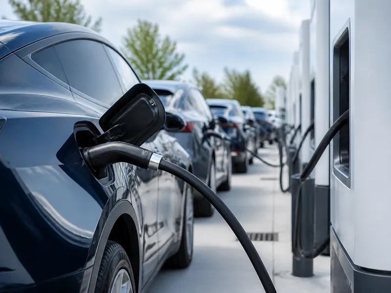
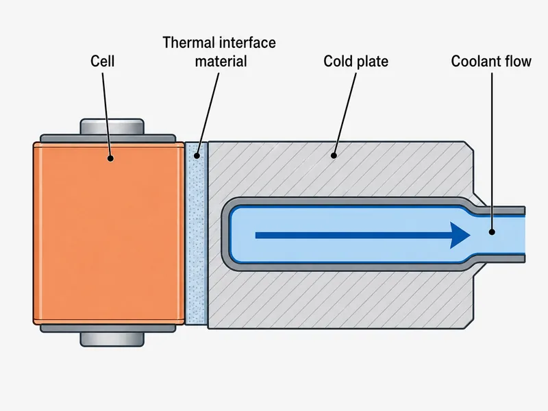
Liquid cooling extends usable EV range mainly by holding cells inside a narrow temperature band and keeping cell-to-cell differences small. It does not add energy to the pack; the gain is a stabilization effect. The benefit travels along a defined heat path: heat leaves each cell, crosses a thermal interface, enters a cold plate, and is carried away by circulating coolant. Every step is an engineering variable a battery-pack team can size and verify. This article covers where liquid cooling sits in that path, when it is actually needed over air cooling, and how the temperature control it provides converts into range and cycle life. It does not cover cell chemistry selection, cabin HVAC, or immersion and refrigerant-direct architectures beyond brief comparison.
How Liquid Cooling Fits the Cell-to-Coolant Heat Path
Liquid cooling works by shortening the thermal resistance between the cell and the coolant, so the heat path decides whether a design succeeds. In a battery pack that path crosses three interfaces, and each one adds resistance: cell casing to gap filler or interface material, interface to cold plate wall, and plate wall to moving coolant. A weak link at any interface caps the whole system. That is why a high-conductivity coolant on its own does not guarantee good cooling.
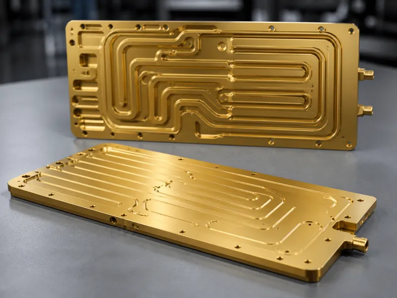
The cold plate couples the pack to the coolant loop, and its job is to spread heat and remove it evenly, not just carry it away. Channel layout, wall thickness, and contact area against the modules set how much heat the plate can pull at a given coolant temperature. Trumonytechs builds this stage of the path with its cooling plates, which sit directly under or between modules to bring coolant close to the cells.
Coolant choice drives the physics at the last interface. Water-glycol mixtures carry heat far better than air per unit volume. Water’s specific heat is on the order of four times that of air, and its density is roughly a thousand times higher. That volumetric advantage is why a compact liquid loop can remove heat a large air duct cannot. It also explains why air and liquid suit different heat loads and are not interchangeable.
Air Cooling vs Liquid Cooling: Where the Line Falls
Air cooling stays the right choice when continuous heat load is modest and pack energy is low, and liquid cooling earns its complexity as heat load and charge rate climb. There is no single industry switch-over point. The boundary depends on pack geometry, airflow capacity, ambient temperature, allowable pressure drop, and the cell-to-cell temperature difference the design can tolerate. The deciding variables are the sustained heat load, the peak C-rate during fast charging or high-power discharge, and that temperature-difference target. Confirm each by test or simulation for the specific pack.
Temperature uniformity is usually the variable that forces the switch. Air struggles to hold a small spread across a densely packed module, because the airstream warms as it travels and cells near the outlet run hotter than cells near the inlet. A liquid loop can hold a tighter spread in a smaller volume, which frees packaging space and can raise energy density. Those packaging and uniformity gains are the practical reasons a team moves to a loop once air can no longer hold the target spread.
The cost of liquid cooling is added mass, plumbing, a pump, and a leak-management burden, so the thermal target should justify it before it is adopted. A useful field habit is to check the worst-case duty cycle first. A pack that only ever sees gentle discharge may never need a loop, while one specified for repeated DC fast charging usually does. The table below frames the decision variables, not fixed numbers, since the thresholds depend on cell format and duty cycle.
| Decision variable | Air cooling | Liquid cooling |
|---|---|---|
| Suitable heat load | Lower sustained loads | Higher sustained loads |
| Cell-to-cell temperature spread | Harder to keep tight | Can be held tighter in less volume |
| Packaging / energy density | Needs airflow channels | More compact loop |
| System complexity and mass | Lower | Higher (pump, plumbing, leak control) |
| Typical fit | Modest duty cycles, lower C-rate | Fast charge, high-power discharge, large packs |
Temperature Uniformity and Why It Drives Battery Life
Holding every cell near the same temperature matters as much as the average, because a temperature gradient makes cells age at different rates and drags down the whole pack. Lithium-ion aging follows an Arrhenius-type relationship, so a hotter cell degrades faster. As a rule of thumb often cited in the literature, the aging rate roughly doubles for each 10°C rise above the comfortable band. When some cells sit warmer than their neighbors, they lose capacity sooner, and the pack ends up limited by its weakest cells.
The optimal operating window is commonly given on the order of 15°C to 35°C, though published sources differ and the exact band depends on chemistry and on whether the goal is peak performance or minimum degradation. For design work the more actionable target is the spread. Many pack teams keep the cell-to-cell difference within about 5°C, and tighter designs aim for 3°C or less. That uniformity target, not a single set-point, is what a cold plate’s channel design gets validated against.
Verifying uniformity is a concrete engineering step. The practical check is to instrument cells at the coolant inlet and outlet ends under the worst-case duty cycle, then confirm the measured spread stays inside the target with margin. If it does not, the usual levers are coolant flow rate, channel geometry, and the interface path. Each of those is examined below.
How Cooling Actually Extends Usable Range
Cooling extends range indirectly, by protecting capacity and efficiency, and the honest framing separates that real gain from the energy the cooling system itself draws. Keeping cells in their comfortable band limits the capacity fade and the rise in internal resistance that come with heat. The pack then holds more of its rated energy over its life and delivers it efficiently on any given drive. This is the mechanism behind range retention, and it makes cooling a life-and-consistency story more than a headline range-per-charge story.
The counterweight is parasitic load. Pumps, fans, and a chiller draw energy from the same battery they protect, so an oversized or poorly controlled loop can give back part of the range it earns. Raising coolant flow shows the tension directly. More flow improves heat transfer and uniformity, but it also raises pressure drop and pump power. Flow is therefore sized against the target temperature spread and an allowable pressure drop, then confirmed over the full duty cycle. Good designs meter cooling to demand instead of running flat out, and they reject absorbed heat through a radiator or a liquid-to-air heat exchanger so the pump can run slower. The variable to watch is net energy: cooling benefit minus parasitic draw, measured over a real drive and charge cycle, not at a single operating point.
Fast charging is where the range-and-cooling link is most visible. High charge currents dump heat quickly, and without adequate heat removal the pack must throttle charge rate to stay safe. That lengthens stops, and over time the added heat accelerates wear that erodes range. A loop sized for the charging duty cycle lets the pack accept higher current inside its temperature limits, so the payoff of liquid cooling often shows up at the charger as much as on the road.
Integrating Cold Plates and Interface Materials in the Pack
The heat path performs only as well as its weakest interface, so integrating the cold plate with the right thermal interface material is where pack-level cooling is won or lost. Cells never sit perfectly flat against a plate, and the air gaps left by mechanical tolerance are strong insulators. A thermal interface material fills those gaps to lower contact resistance. Its selection depends on the gap size, the flatness and assembly stress of the joint, and whether the material also needs to bond or stay reworkable.
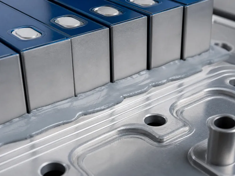
Matching the interface material to the cell format keeps the path consistent across the module. A pack of large prismatic cells presents different flatness and gap conditions than cylindrical cells, so the gap-filler thickness and conductivity are chosen against those conditions, not copied between designs. A component menu misses this integration view: the plate, the interface material, and the cell geometry work as one system, and conduction-based cooling only reaches the coolant efficiently when all three are matched.
Trumonytechs approaches this stage as a matched set and supplies both the cold plates and the interface materials that sit between the cells and the plate. For an engineering team, the value of designing them together is a heat path treated as a single system, so contact resistance and temperature spread are set by design intent and then confirmed by test on the actual build. Where a specific gap, stress, or bonding requirement applies, the interface material should be selected on those stated conditions; a product-family default can miss them.
Conclusion
The core judgment to carry away is that liquid cooling improves EV range by stabilizing the pack, not by feeding it. Its value comes from the whole cell-to-coolant heat path, not from any single component. Air cooling is enough for modest, low-C-rate duty. Liquid cooling is warranted when heat load, fast-charge current, or a tight cell-to-cell temperature target exceed what a given airflow design can hold. The most common misreading is to credit liquid cooling with a direct range boost, when the real levers are capacity retention over life, consistent efficiency, and headroom to fast charge without throttling. A design team gets there by fixing the uniformity target first, then validating flow rate, plate geometry, and the thermal interface against the worst-case duty cycle.
FAQ
Is air cooling ever enough, or do fast-charging packs always need liquid cold plates?
Air cooling can be enough for packs with modest heat loads and lower charge rates. Repeated DC fast charging, though, often pushes heat load and temperature spread beyond what a given airflow design can manage. The deciding factors are the worst-case C-rate and the cell-to-cell temperature difference the design must hold, so the check is to evaluate the hardest duty cycle, not the average one.
How tight does cell-to-cell temperature uniformity need to be?
Many battery-pack teams target a cell-to-cell temperature difference within about 5°C, and tighter designs aim for 3°C or less, because uneven temperatures make some cells age faster and limit the whole pack. The exact target depends on cell format and duty cycle. Confirm it by instrumenting cells at the coolant inlet and outlet under worst-case load.
Does the cooling system’s own energy use cancel out the range it saves?
Not automatically, and you cannot judge it from the choice of liquid cooling alone. The answer is the net energy over a full drive-and-charge cycle: the capacity and efficiency the cooling protects, minus the pump, fan, and chiller draw. An oversized or always-on loop can give back much of that gain. Confirm the balance with measurement or a system model over the real cycle before assuming it is positive.
Which interface variables decide the heat path when integrating cells, TIM, and a cold plate?
Contact resistance is set mainly by the gap size between cell and plate, the flatness and assembly stress of the joint, and the conductivity and thickness of the thermal interface material. Those conditions differ by cell format, so the interface material is selected against the specific gap and stress, not reused from another pack.
Further Reading
- Electric Vehicle Batteries (U.S. DOE Alternative Fuels Data Center) — U.S. Department of Energy. Reference on lithium-ion EV batteries and why temperature affects their performance and life.
- How Do All-Electric Cars Work (U.S. DOE Alternative Fuels Data Center) — U.S. Department of Energy. Describes the EV thermal system that keeps the battery and power electronics within a proper operating temperature range.
Related Articles
- Integration And Optimisation Of Intelligent Cooling Systems — Shows how liquid cooling plates combine with sensors and controls to hold pack temperatures, the system layer above the heat path described here.
- Basic Principle of Liquid Cooling Plate — Explains how a closed liquid loop moves heat through pumps and piping, the fundamentals behind the cold-plate stage.
- Difference Between Heat Sink and Cold Plate — Clarifies when an air heat sink or a liquid cold plate fits, based on thermal budget, space, and airflow.
- What is a Battery Cold Plate? — Defines the battery cold plate and how it pulls heat from cells by direct contact to keep packs in range.
- Comprehensive Comparison of Liquid Cooling Plates vs. Traditional Cooling Technologie — Compares direct-contact liquid cooling with air cooling on heat-transfer efficiency and packaging for dense EV packs.
