
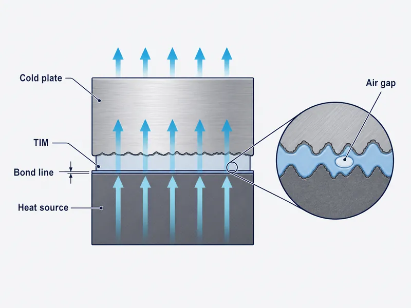
The most useful innovation in thermal interface materials is not a higher headline conductivity number but a material that actually moves heat across a real, uneven joint. As power electronics and battery packs get denser, the heat path from a die or a cell to a heat sink or cold plate runs through a thin, imperfect gap, and a thermal interface material (TIM) exists to fill that gap and displace the air trapped in it. Air conducts heat at roughly 0.026 W/mK, so even a microscopically thin air layer dominates the interface. The recent advances worth tracking (hybrid carbon fillers, boron nitride, liquid metals, and engineered polymers) matter to an engineer only to the extent they hold up under the gap, assembly stress, and verification a production build imposes.
The scope here is deliberately narrow. It is written for battery-pack and power-electronics engineers choosing a TIM for the cell-to-coolant or die-to-sink path, and it does not cover coolant flow, cold-plate hydraulic design, or specific product datasheets; those depend on your architecture and should be checked against qualified test data.
What Thermal Interface Materials Do in the Heat Path
A TIM’s job is to lower the contact thermal resistance between two surfaces that are never truly flat. Machined and molded surfaces touch only at scattered high spots, and air fills the rest of the interface. A TIM wets into those voids so heat conducts through material instead of across an insulating air film, which is what lets a heat sink draw heat out of the junction it is bolted to.
TIMs come in several families, and each trades performance against handling. Thermal greases and pastes flow to a very thin bond line and give low resistance but can pump out or dry over thermal cycles; gels and dispensable gap fillers cure in place and tolerate larger, uneven gaps; pads and phase-change materials ease assembly at some cost in bond-line thickness; thermally conductive adhesives add structural bonding on top of heat transfer. Choosing among the different types of thermal interface materials starts with the gap you actually have, not the conductivity you wish you had.
Material Advances Reshaping TIM Performance
The material story of the last decade is about raising a composite’s usable conductivity without losing the compliance and processability a real assembly needs. The four families below are where most of that work has concentrated.
Hybrid carbon TIMs
Hybrid carbon TIMs disperse carbon nanotubes or graphene into a polymer or grease matrix to build conductive pathways through the joint. The numbers here are worth pinning down. The intrinsic conductivity of individual carbon nanotubes or graphene sheets can exceed 2000 W/mK, but the finished composite TIM delivers far less, because the interfaces between filler particles and the matrix dominate the result. A 2022 review in *Nanomaterials* catalogs research-grade carbon composites in the range of tens to a few hundred W/mK (for example, vertically aligned graphene structures around 50 W/mK and graphene monoliths near 500 W/mK), not the intrinsic filler value. Treat any “2000+ W/mK” figure as a property of the nanomaterial, not of the hybrid carbon TIM you can actually dispense.
Boron nitride and other nanomaterials
Boron nitride nanosheets are valuable when a joint must conduct heat and block current at the same time. Hexagonal boron nitride combines high thermal conductivity with genuine electrical insulation and chemical stability, which makes it a common filler where a metal-loaded or carbon-loaded TIM would risk a short. In battery and power-module work that dual requirement is routine, because the interface often sits between a live surface and a grounded cold plate, and the TIM has to carry heat without becoming a leakage path.
Liquid metal TIMs
Liquid metal TIMs give very low thermal resistance but bring handling risks that decide where they belong. Gallium-based alloys stay liquid near room temperature, wet surface asperities well, and reach conductivity far above conventional grease. The catch is that they are electrically conductive and can corrode aluminum, so a stray bead can short adjacent traces or attack a cold-plate surface. They earn their place in tightly controlled, high-flux joints rather than in open, vibration-heavy assemblies.
Polymer-based gap fillers and pads
Polymer-based TIMs remain the workhorse for battery packs because they balance conductivity with compliance and dispensability. Silicone and silicone-free elastomers loaded with ceramic or other fillers typically land around 1–5 W/mK, with dispensable cell-to-pack gap fillers often specified in the low single digits depending on chemistry and loading. The engineering value is not the peak number but that these materials fill millimeter-scale, non-uniform gaps at low assembly stress and cure without solvents, which a pack line needs as much as raw conductivity.
Matching a TIM to the Assembly: Gap, Stress, Curing, and Insulation
Pick a TIM by the constraints of the joint first, then compare conductivity within the shortlist that survives. In pack and module assembly the gap a TIM must fill is rarely uniform: cell-height tolerance and cold-plate flatness set the real bond line. A material chosen only on its datasheet W/mK can still underperform if it cannot wet that gap at the clamp pressure available. Start by fixing the gap range and flatness, then the load the cells and structure can take, then whether the interface must also insulate or bond.
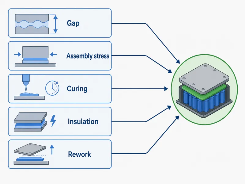
Several variables usually decide the family before conductivity does. The gap and its variability separate thin-bond greases from thick-section gap fillers. Assembly stress rules out stiff materials where soft cells or long tolerance stacks cannot take the load. Curing behavior, whether two-part cure-in-place or a pre-formed pad, drives takt time and reworkability, and reworkability matters when a module has to come apart for a fault.
Insulation status decides whether a conductive filler is allowed at all. Where a supplier’s data or your own qualification shows a formulation releases low-molecular-weight siloxanes, those volatiles can foul nearby humidity or gas sensors, and teams then move to silicone-free fillers and validate the different dispensing behavior. Working through these constraints in order is the substance of choosing the right thermal interface material for an application, and it is where Trumonytechs’ TIM range is meant to be matched to the cell-to-coolant path instead of picked on a single number.
Verifying Real Thermal Performance
A datasheet W/mK describes the material alone, so verify the joint by its thermal impedance at your real bond line. Two materials with the same nominal conductivity can behave differently once contact resistance and achievable thickness are included. A higher-conductivity TIM sometimes yields a worse joint if it will not thin out or wet under the available pressure. The property that predicts field behavior is through-thickness impedance at the clamp pressure and thickness you will actually build.
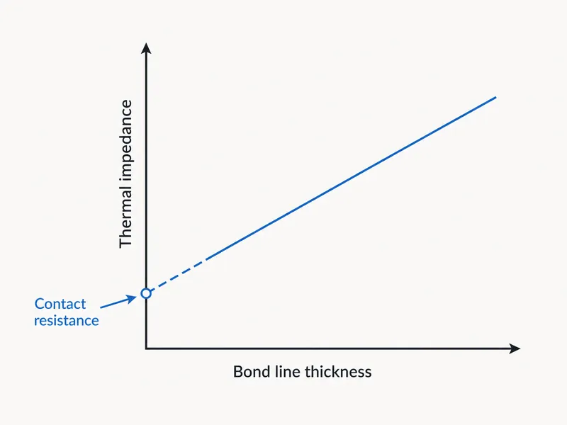
The standard reference method makes this measurable. Per ASTM D5470, thermal impedance is measured on a specimen at several thicknesses and plotted against thickness; the slope gives apparent conductivity, and the extrapolation to zero thickness gives the contact resistance the interface adds on its own. The method covers thin conductive materials over a wide thickness range, and it is the reason a serious TIM comparison quotes impedance versus bond line, not a single conductivity headline. Ask suppliers for D5470-style data at a bond line near yours, and confirm it after thermal cycling, not just as-built.
Advanced TIMs in High-Power Electronics and EV Battery Packs
Advanced TIMs matter most where heat flux is high and reliability requirements are strict, which is exactly the profile of power electronics and battery packs. The material choice here is a system decision: the interface has to survive the same vibration, humidity, and thermal cycles as everything around it, without pumping out, drying, or embrittling.
High-power electronics and data centers
In high-power electronics the interface is often the limiting resistance in the whole heat path. The same 2022 *Nanomaterials* review notes steady-state heat fluxes on the order of 150–200 W/cm² in high-power integrated electronics, with transient loads that can exceed 400 W/cm². At those densities a poor interface throttles the device regardless of how good the heat sink is, so data-center processors, telecom power stages, and converters are where low-impedance TIMs earn their cost.
EV battery packs and the cell-to-coolant path
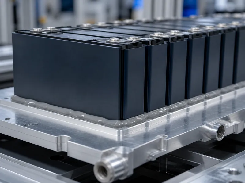
In EV and stationary storage packs the TIM sits between cells or modules and a cold plate, and it balances heat transfer against structure and weight. Gap fillers bridge the uneven space between cells and the plate; thermally conductive adhesives add bonding where the interface is also structural. The design tension is real: more filler raises conductivity but stiffens the material and adds mass, while cells and long tolerance stacks limit how much stress the joint can take. This is the same heat path that battery safety and liquid cooling systems depend on, and getting the interface wrong shows up as hot cells and uneven temperature across the pack long before it shows up as an outright failure.
Conclusion
The practical takeaway is to size the interface before you shop for conductivity: fix the gap and flatness, the assembly stress the cells can bear, and whether the joint must insulate or bond, then compare candidates on thermal impedance at that bond line, not on a headline W/mK. The innovation that matters is a material that holds those properties through real thermal cycling, not the largest number on a slide. The single most common misread in this field is treating a filler’s intrinsic conductivity, the 2000-plus W/mK of a carbon nanomaterial, as if the finished TIM delivered it; the composite never does, and buying on that number leads to interfaces that disappoint in the pack. Decide the constraints first, verify with D5470-style impedance data, and the material choice becomes a comparison you can defend.
FAQ
Do I need a gap filler or a thermally conductive adhesive for a battery module?
Choose by whether the joint must carry structural load, not just heat. A dispensable gap filler is right when the interface only needs to conduct heat across an uneven gap; a thermally conductive adhesive is right when the same interface also has to bond cells or modules to structure. If you need both heat transfer and bonding, the adhesive route is usually the starting point, with conductivity traded against bond strength.
What thermal conductivity is realistic for a dispensable TIM versus a lab-scale carbon TIM?
Expect low single digits in W/mK for a production dispensable gap filler, not the hundreds or thousands cited for research carbon materials. Loaded polymer gap fillers commonly fall around 1–5 W/mK, while the very high figures quoted for carbon nanotubes or graphene are intrinsic filler properties measured in the lab, not what a dispensable composite delivers in a joint.
How is a TIM’s real thermal performance verified?
Verify it by thermal impedance at your bond line, typically using ASTM D5470. The method measures impedance across several thicknesses and separates the material’s apparent conductivity from the contact resistance it adds, which predicts joint behavior far better than a single conductivity number. Ask for data at a bond line close to yours and re-check it after thermal cycling.
Can a higher W/mK TIM make a joint worse?
Yes, if the higher-conductivity material will not reach a thin, well-wetted bond line at your clamp pressure. Thermal performance is impedance, not conductivity alone, so a stiffer or thicker high-W/mK material can leave more contact resistance than a softer, lower-rated one that conforms and thins properly.
What changes when moving from a silicone to a silicone-free gap filler?
Silicone-free fillers avoid the siloxane outgassing that some silicone formulations release, which can foul nearby humidity or gas sensors, but they change dispensing and curing behavior. Where your assembly has sensors vulnerable to that outgassing, silicone-free chemistry reduces that specific contamination path; in exchange you validate the new material’s cure profile, adhesion, and rework properties for your line.
Further Reading
- ASTM D5470, Standard Test Method for Thermal Transmission Properties of Thin Thermally Conductive Solid Electrical Insulation Materials — ASTM International (standard). Defines the thermal-impedance-versus-thickness method this article recommends for comparing TIMs at a real bond line.
- Recent Advances in Thermal Interface Materials for Thermal Management of High-Power Electronics — *Nanomaterials*, 2022 (peer-reviewed review). Supports the composite conductivity ranges and the 150–200 W/cm² heat-flux figures cited for high-power electronics.
Related Articles
- Ceramic Thermal Paste: What It Is, How It Works, and When to Use It — Explains where a ceramic-filled, electrically non-conductive paste fits and when to reach for it.
- Conductive vs Non-Conductive Thermal Paste: A Selection Guide — Helps decide when a joint can tolerate an electrically conductive paste and when it cannot.
- Phase Change Thermal Pad: Transition Band, Clamp Pressure, and Bond Line — Covers the transition band, clamp pressure, and bond line that govern phase-change pad performance.
- What Is Thermal Paste Made Of? — Breaks down the fillers and carriers behind a paste’s conductivity and handling.
- Thermal Paste Alternative: Engineered Options and How to Choose — Reviews engineered alternatives to thermal paste and how to choose among them.