
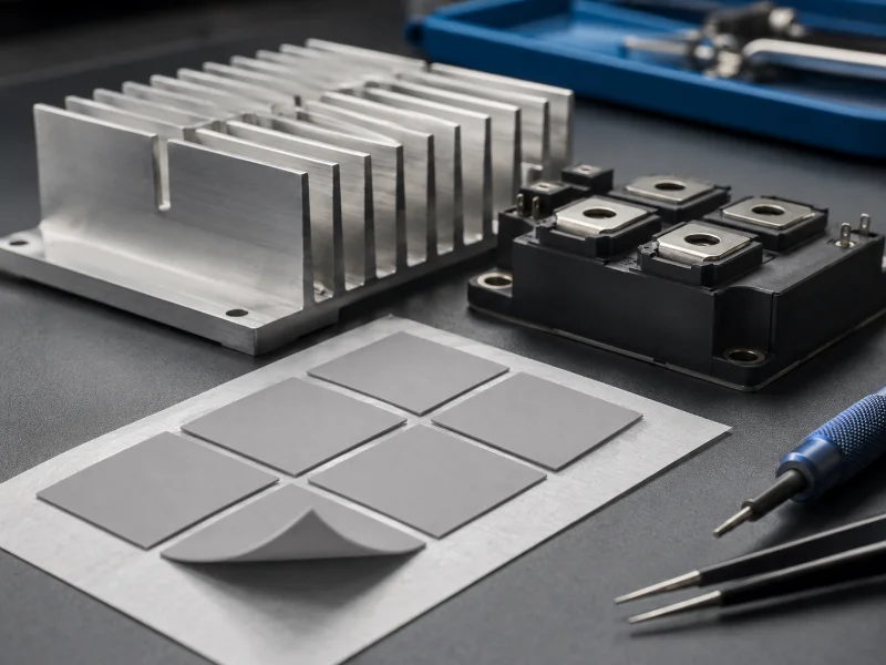
A phase change thermal pad is a thermal interface material that ships as a handleable solid and softens at a grade-specific transition band, commonly published somewhere between 40 °C and 70 °C, so it wets both mating faces and thins under clamping load. Whether it beats the grease you are using now depends on three conditions that have little to do with the largest number on the datasheet. The interface has to complete that transition at least once under sustained clamp, in a production burn-in or in service; the mounting hardware has to deliver and hold clamping load; and the two faces have to be flat enough for the layer to bridge. What governs performance is the bond line after compression.
| Specification | Figure |
|---|---|
| State at room temperature | Solid, handleable, die-cuttable sheet |
| Transition band (softening) | Grade-specific; commonly published between about 40 °C and 70 °C |
| Preconditioning requirement | One full transition under sustained clamp, in burn-in or in service |
| Nominal supplied thickness | Varies by family; thin films from around 0.1 mm, other families to about 1.0 mm |
| Same chemistry also supplied as | Stencil-printable paste, solvent added for printing |
| Impedance test basis | ASTM D5470-17(2024): steady-state thermal impedance, liquid compounds through hard solids; phase change materials fall under its Type I |
| Electrical isolation | Not inherent; non-conductive and dielectric-rated are separate specifications |
| Air, for reference | About 0.026 W/m·K, more than two orders below a filled pad |
Ranges span several supplier families, not one datasheet. Read transition band, thickness and clamp requirement from the documentation for the grade you shortlist.
What a Phase Change Thermal Pad Does at the Bond Line
A phase change pad trades room-temperature handling convenience for grease-like conformity, and the trade completes only after the interface has passed through the material’s transition band while under clamping load.
Two machined faces that look flat to the eye touch across a small fraction of their nominal area. The rest is air, the worst conductor in the assembly. A solid pad placed between them is easy to position and cuts cleanly to shape, and under light clamp it conforms to some of the surface profile. What it has not reached is the wetted, minimum bond line its datasheet figures describe.
Heat completes it. Above the transition band the polymer matrix loses viscosity, wets both faces, and flows outward under the clamp until the layer between them is thin. On cooldown the material firms up and holds the geometry it settled into, which is why these pads resist the migration that pushes grease out of a joint over repeated cycles. That geometry persists once established, so the transition is a commissioning event rather than a continuous operating requirement.
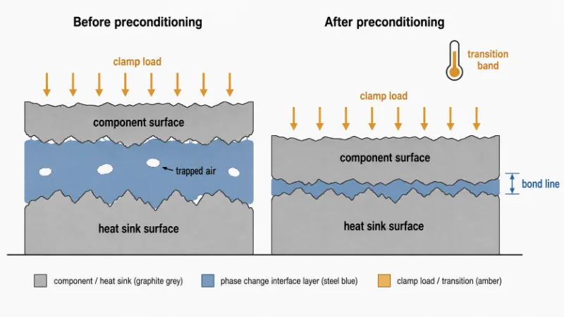
Clamping load is therefore an input to the thermal result. Pressure sets the final bond line, and bond line sets the bulk resistance term. Logging case temperature rise after a controlled soak at load validates the assembled thermal result. That number will not separate bond line, contact pressure and surface flatness on its own, because several combinations of the three produce similar temperature differences.
Two Different Meanings of Phase Change in Thermal Datasheets
The words phase change carry two unrelated meanings in thermal engineering, and interface datasheets use the softening sense, which sets what the material can do for a given bond line and duty cycle.
In energy storage, a phase change material is chosen for latent heat: it absorbs a large quantity of energy at nearly constant temperature while it melts, then gives it back on freezing. In interface work the engineering purpose is wetting and bond-line reduction. Most current grades do not liquefy at all. They soften enough to conform and thin.
The size of that difference is easy to bound. Take the most generous case possible: a 0.2 mm layer that is entirely paraffin, not a heavily filled composite. At roughly 0.9 g/cm³ and a latent heat of fusion near 200 kJ/kg, one square centimetre of that layer stores about 3.6 J through its transition. A die dissipating 20 W/cm² consumes that in under a fifth of a second. Real pads carry ceramic filler, so the actual figure sits well below that. The number is our own arithmetic on published constants for paraffin, not a measured storage capacity, so treat it as an order-of-magnitude bound.
On boards where a transient spike is the real complaint, the interface layer is usually the wrong place to look first. A softening pad lowers steady-state resistance across the joint, while the thermal mass that rides out a spike lives in the spreader and the sink.
Phase Change Pad, Thermal Grease, and Elastomeric Gap Pad Compared
Three interface materials cover most board-level joints, and the choice turns on the gap being filled, the clamping load available, and whether the joint will be opened again in service.
| Phase change pad | Thermal grease | Elastomeric gap pad | |
|---|---|---|---|
| Gap it suits | Thin, near-contact joints once softened | Thinnest joints, micron scale | Real mechanical gaps, tenths of a mm and up |
| How it conforms | Softens above the transition band, flows under load | Conforms immediately, no temperature threshold | Compresses elastically, needs deflection force |
| Under thermal cycling | Holds position after cooldown | Prone to pump-out over repeated cycles | Holds position, may take a compression set |
| Assembly | Peel and place; needs sustained clamp plus one heat soak to reach rated impedance | Dispensed or stencilled; volume control governs the result | Peel and place; thickness selected to the gap |
| Rework | Fresh pad on reassembly unless the supplier validates reuse | Clean off and reapply | May be reusable if supplier and application permit |
Here is the case against specifying a pad. If the joint will never see its transition condition, in a burn-in step or in service, the layer never reaches the impedance printed on its datasheet. A well-applied thermal grease is then cheaper and performs better from first power-on. The same holds for a prototype you expect to open again next week.
Why Datasheet Conductivity Is a Comparison Basis, Not a Performance Prediction
Published thermal conductivity for a phase change pad describes bulk material under a controlled test geometry, and it predicts assembled performance only when your surfaces and pressure resemble the fixture’s.
The relevant standard is ASTM D5470-17(2024), currently active, covering steady-state thermal impedance and apparent conductivity for thermally conductive electrical insulation materials, from liquid compounds through hard solids. Its significance section states that it imposes an idealised heat flow pattern and a specified average specimen temperature, and that impedances measured this way cannot be applied directly to most practical applications. The standard is telling you, in its own words, that the number is a ranking basis.
The standard also documents how conductivity is extracted: impedance is measured at several thicknesses, apparent conductivity is the inverse of the slope, and the intercept at zero thickness is the sum of the two contact resistances. That model can be approximated as R ≈ t/k + R_contact, assuming uniform parallel heat flow and ignoring lateral spreading. Because the intercept is measured against lapped fixture faces, a warped production lid adds a contact term the published figure never contained.
Run the arithmetic both ways. Moving from a 200 µm to a 300 µm bond line on a pad published at 6 W/m·K adds 100 µm ÷ 6 W/m·K, about 0.17 °C·cm²/W of bulk term. Leaving 20 µm of air unfilled instead, at roughly 0.026 W/m·K, costs about 7.7 °C·cm²/W over that area, near 45 times the penalty. Thicker is therefore not automatically worse, and on a lid with genuine warpage the thicker pad can win. Both numbers are arithmetic on published constants rather than bench measurements. Put your own values through the same expression: divide your candidate bond line in metres by its published W/m·K, then weigh the result against the air you would otherwise be bridging.
Before we shortlist grades for a customer, we measure the load the mounting hardware actually delivers and the flatness of both faces. Those two inputs move assembled impedance further than the spread between most published conductivity figures.
Variables That Decide Whether a Phase Change Thermal Pad Will Work in Your Assembly
A phase change pad succeeds or fails on assembly conditions more than on grade selection, and three of them have to converge: preconditioning reachability, sustained clamping load, and the flatness of the two mating faces.
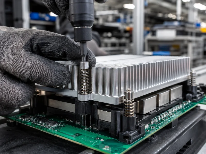
Two lock first. Preconditioning reachability locks first because it is an input to every other choice: if the joint cannot be brought through one full transition under load, no grade or thickness recovers it. The clamping arrangement locks alongside it, because spring-loaded fasteners, fixed screws and the boss they thread into are tooling decisions, fixed once the enclosure exists. Flatness measurement and grade selection follow. None of the three governs the others; these two are simply the ones you cannot revisit cheaply.
| Assembly scenario | Phase change pad | Condition attached |
|---|---|---|
| Power module or processor running steadily above the band, rigidly clamped | Suits | Clamp must hold load through thermal cycling, not only at torque-up |
| Low-duty device that idles below the band and spikes briefly | Suits with a process step | Add a production burn-in soak, or move to a lower-transition grade |
| Large or warped lid, non-flat baseplate | Suits, with thickness chosen to the profile | Measure actual flatness; a thicker pad may beat a thinner, higher-conductivity one |
| Joint with a real mechanical gap of several tenths of a mm | Poor fit | Gap pad or gap filler covers deflection a phase change layer is not built to take |
| Assembly opened routinely for field service | Suits with a caveat | Budget a fresh pad each time the joint is broken |
When the preconditioning soak is skipped or cut short, at least two failure modes follow. The material may never fully wet, leaving impedance well above the qualified figure. Or it wets only over local hot spots, producing a bond line consolidated in places and open in others. Check a third possibility as well, since a clamp that relaxed before the material had time at temperature produces the same symptom from a different cause.
If Your Joint Can Be Preconditioned, a Phase Change Pad Is Worth Sampling
A phase change thermal pad is worth sampling when the interface can complete one full transition under sustained clamp and the mounting hardware holds that load through thermal cycling. Grade, thickness and die-cut shape all stay open once those two answers exist, and conductivity ranking is the last input, not the first.
Pads get specified on the assumption that the interface gets hot enough. When nobody checks that assumption against the real duty cycle or backs it with a burn-in step, the result is a bond line that never fully wets. The correction at that point is a process or mounting change, which is why the assumption deserves testing before the grade is chosen.
Which move is yours depends on the case temperature and the gap you measured. If the joint runs steadily hot and the clamp is spring-loaded, sample a phase change pad against your current grease at your own bond line and pressure. If case temperature is marginal, decide between adding a burn-in soak and moving to a lower-transition grade, and where neither is practical, grease or another of the thermal paste alternatives is the right answer. If you are bridging a real mechanical gap, the search belongs in the thermal conductive pad family, where thickness is selected to the gap.
We compare candidate grades against the load and flatness a customer’s own hardware delivers, because a shortlist built on published conductivity alone rarely survives the first sample build. What that comparison will not tell you is whether the sink or cold plate on the far side of the joint has the capacity your device needs, which stays a separate thermal-budget calculation.
FAQ
Can a phase change thermal pad be reused after the heat sink comes off?
Normally no. The layer has taken the exact contour of that joint, and breaking it leaves a face that will not re-wet cleanly. Briefly lifting a sink to check something is a different case from a reassembly that has to hold for years.
Can a production burn-in replace a hot duty cycle?
Often, yes. Suppliers publish a soak temperature and dwell for exactly this reason, and an oven or heated fixture can complete the transition before the board ships. The soak only counts if the clamp sits at full load throughout and the temperature clears the transition band with margin.
Are phase change thermal pads electrically insulating?
Electrical isolation is not inherent to this family. Some grades are electrically non-conductive, while dedicated grades built on a reinforcing carrier are designed and qualified as dielectric barriers. If isolation is a requirement, verify dielectric strength, breakdown voltage and carrier construction at your intended bond line, since a very thin post-transition layer reduces the separation the isolation depends on.
Do unused pads have a shelf life?
Yes, stated in months for most grades, alongside storage temperature and humidity conditions. Expired stock is not automatically unusable, but it sits outside the supplier’s performance warranty, so treat it as unqualified material.
How does the pad behave when the assembly is mounted vertically?
Vertical suitability is grade- and temperature-dependent. The material firms up below its transition band and holds position. Grades differ in how far they spread under sustained heat and load, so ask for a flow-out or bleed figure when the assembly sits vertical at temperature.
