
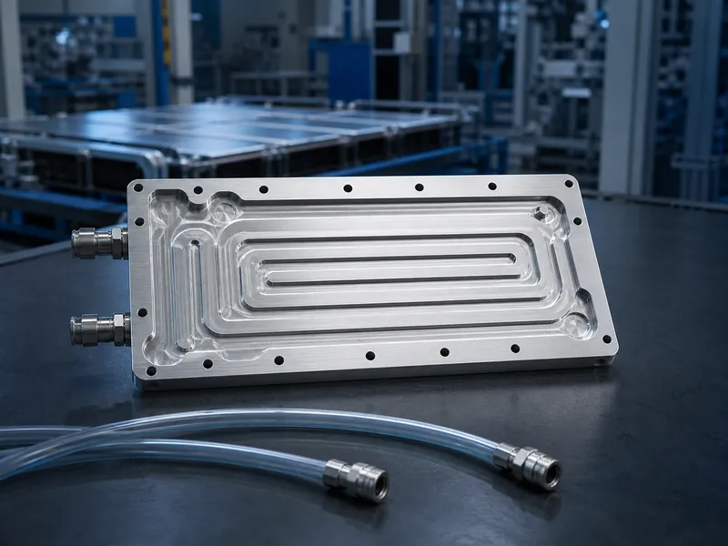
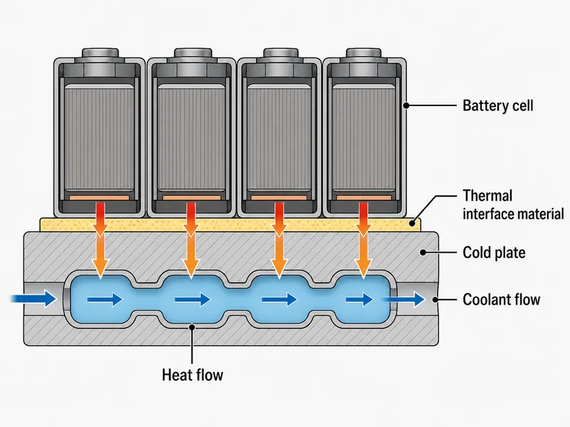
A cold plate is a sealed metal plate that carries liquid coolant through internal channels to pull heat out of a device. In a battery pack it sits in the middle of the heat path. Heat leaves the cells, crosses a thermally conductive interface material, enters the plate wall, and the coolant carries it away. The coolant never contacts the cells; the plate reaches the module through the interface material, which places it in the non-contact branch of liquid cooling, alongside contact methods such as immersion and spray. Good design comes from matching the plate’s material, channel layout, and manufacturing process to a defined heat load and temperature target, not from picking a generic part.
Where Cold Plate Cooling Fits in Battery Thermal Management
A cold plate only cools what it physically contacts, and that contact constraint is what makes the design decisions matter. Heat moves from the module into a single-phase coolant circulating through the plate, so plate flatness, interface quality, and channel routing carry the performance. Three properties decide whether a plate suits a given pack:
- Contact interface: plate flatness, the gap to the module, and interface-material quality govern the contact thermal resistance.
- Packaging: a water cooling plate has to fit the cell format and module geometry, and cylindrical, prismatic, and pouch cells each present a different contact surface.
- Coolant boundary: because the coolant is sealed inside the plate, electrical isolation, sealing, and leak margins are part of the design, not afterthoughts.
Whether a cold plate is cheaper than another cooling approach is a system question, not a property of the plate. It depends on the coolant, sealing, pump, and maintenance the system needs, so the comparison has to be made at pack level.
Common Cold Plate Types and How They Are Made
The manufacturing process is the first design decision, because it fixes the achievable channel geometry, pressure rating, weight, and cost before any thermal tuning. Each of the five processes below fits a specific mix of heat load, strength, and production volume. The strengths and weaknesses noted are tendencies to verify against your alloy, wall thickness, and duty cycle, not fixed ratings.
Profile Extrusion with Friction Stir Welding
The profile-extrusion route shapes the channels directly, machines them open, then seals the cover with friction stir welding. The solid-state weld tends to give good structural strength, surface flatness, and reliable heat transfer at volume. The costs are real: more machining, a thicker and heavier plate, more space, and limited room for screw holes on the sealing face. This route fits packs where structural load and joint integrity outweigh weight.
Harmonica Tube Plates
Harmonica-tube plates extrude aluminium into parallel micro-channels and weld the ends to collectors. That keeps them light, low in tooling cost, and fast to produce. The trade-off is a small contact area, thin walls, a modest heat-exchange coefficient, and weak load bearing, so they tend to suit light, cost-driven modules away from the highest-flux zones.
Roll-Bond (Blow-Up) Plates
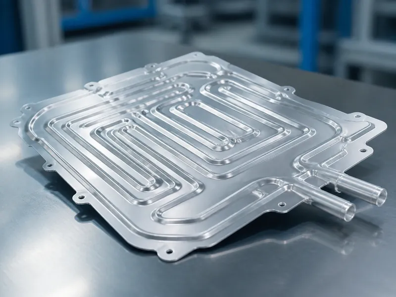
Roll-bond plates print a channel pattern between two sheets, hot-roll them together, then inflate the channels with gas. They are inexpensive at volume, transfer heat well, and can be made very thin and light. Their weakness is mechanical: the inflated structure has limited pressure resistance and a higher leakage risk, which keeps them in low-pressure, thickness-constrained layouts.
Stamped Plates
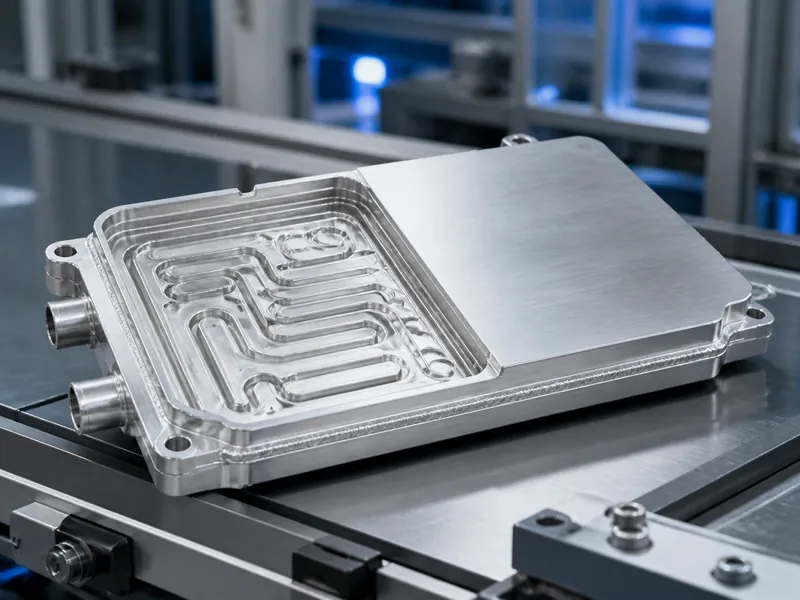
Stamped plates press aluminium between dies to form channels, then braze the two shells together. The die approach allows a wide range of channel shapes, a large contact area, and good pressure and strength resistance at volume. It carries tooling cost and needs tight flatness control, and the same flatness that helps thermal contact makes assembly less forgiving. Stamped plates match high-volume, cell-to-pack layouts where the tooling is amortised.
Plate-and-Fin Plates
Plate-and-fin plates fill the space between two panels with serrated fins and seal them by flux-free vacuum brazing. This yields high internal cleanliness, even flow distribution, and strong heat-transfer performance. The cost is higher and the flatness requirement is demanding, so this route is chosen where heat-flux density and temperature uniformity justify the expense.
Choosing the Plate Material: Aluminum or Copper
Aluminium is the usual choice for a battery cold plate because pack weight matters more than peak conductivity. Copper conducts heat roughly twice as well, sitting near 400 W/m·K against about 150–250 W/m·K for aluminium alloys depending on alloy and temper, but it is heavier, costlier, and harder to machine. Copper earns its place only where local heat flux is high enough to need it; elsewhere aluminium recovers conductivity through channel design. Whichever metal is used, it has to be chemically compatible with the coolant to avoid galvanic corrosion, so coolant selection is decided together with the plate metal, not after it.
Thermal Factors in Cold Plate Design
Cold-plate design follows the same logic as an air-cooled heat sink, with one change that drives everything: the working fluid is a liquid, which raises the achievable heat-transfer coefficient and changes how the geometry is optimised. Four factors are under the designer’s control in every plate:
- contact area between solid and fluid within a fixed volume;
- the thermal path from the heat source through the interface material;
- the shape of the fluid-to-solid surface for effective wetting;
- a short conduction path from source to plate wall to coolant to system exit.
The four factors above are tuned to hold cells inside a target temperature band. Peer-reviewed battery thermal-management reviews commonly cite a design target window of roughly 15–35 °C for lithium-ion cells, though some sources state it as 20–40 °C and the acceptable range is wider still; the exact limits depend on cell chemistry, state of charge, C-rate, and manufacturer specification. The same reviews commonly target keeping the temperature spread between cells within about 5 °C. That figure is a pack-level uniformity goal, separate from the temperature difference inside a single cell and from the absolute upper limit. These are design targets, not universal safety limits.
The design inputs separate into four categories that should not be conflated: the heat-load distribution (uniform or concentrated), the coolant flow rate and pump curve, the allowable pressure drop, and the temperature acceptance criteria (a maximum surface temperature, and separately whether that surface must be uniform). Real requirements combine them into recognisable cases:
- Uniform heat flux, fixed flow, a capped pressure drop, and a maximum surface temperature, with no requirement that the surface be uniform.
- The same hydraulic limits, but with heat loads concentrated in hot spots under the component, so the thermal map is non-uniform.
- Uniform heat flux and fixed flow within the pressure cap, with non-uniform surface temperature accepted across components.
- Any of the above, plus a requirement that the surface temperature difference stay within a set uniformity limit, across the whole plate or under a chosen component.
The cases that demand surface uniformity are the most complex and costly to satisfy; the two that accept non-uniform surface temperature are more common on fixed cooled panels. Working a case to closure means building a thermal map, forming a liquid-circuit concept, calculating the temperature rise and pressure drop, and adjusting the circuit route until the numbers meet the targets. The design is then simulated, and a prototype is built and tested for pressure drop, inlet and outlet temperatures, and the temperature difference between the plate surface and the pack. That test confirms feasibility before mass production.
Flow Channel and Runner Design
Flow-path direction sets both the direction and the efficiency of heat transfer, so runner design decides plate performance once the process and material are fixed. The route is defined first: lay out the liquid circuit, then calculate temperature rise and pressure drop before committing it. Material selection runs alongside, weighing cost, availability, and machinability against thermal conductivity and density. The coolant’s own properties, including its freezing and boiling points and its chemical compatibility, are a separate check that belongs to the fluid, not the plate metal.
With the route set, the channel layout is tuned against competing variables:
- keep the fluid close to the heat source to cut spreading resistance;
- route channels a safe distance from fixing holes and structural features;
- sweep the coolant evenly so the whole heat-transfer area is used;
- raise flow rate where a higher convective coefficient is needed, accepting the pressure-drop penalty;
- combine series and parallel channels to manage flow resistance and distribution.
Channel geometry is one of these levers; straight and inclined channel layouts trade local heat transfer against pressure drop differently. Whether a series-parallel split actually lowers resistance and evens out flow depends on branch length, cross-section, the manifold, the fittings, and the operating point, so it is checked against the pump curve instead of assumed. Higher flow lifts the heat-transfer coefficient but costs pump pressure, and tighter channels near the source improve local cooling but can starve flow elsewhere. The calculation-and-simulation loop is what resolves those trade-offs.
Reducing Cold Plate Complexity and Production Cost
The drawing stage sets cost, so control comes from settling the plate style, runner arrangement, cooling-area distribution, and production process before tooling, not from thinning material afterwards. The controllable trade-offs run between lifecycle cost, production volume, tooling and NRE, machining, joining, leak testing, pump power, and maintenance. The order matters: verify the thermal, hydraulic, and structural boundaries the plate must meet first, then look for complexity that can be removed without breaching them.
Demanding requirements do not always point to a simpler plate. Very high heat-dissipation power, rapid temperature cycling, or tight safety margins on the cells may call for more manifolding, redundancy, joint control, or leak verification, not less. Simplifying the plate lowers cost only where it does not compromise those verified boundaries.
A workable method is to start from the customer’s thermal parameters, choose the plate style and process that meet them with the least necessary complexity, and validate by simulation and test before committing tooling. Supporting components such as liquid-cooled cases, interface pads, connectors, and manifolds are then matched to the same design, so the plate is not optimised in isolation from the pack it serves.
Conclusion
Cold plate design for thermal management is a chain of linked choices, not a single spec: choose the manufacturing process that fits the heat load and strength need, default to aluminium unless the heat flux justifies copper’s weight, then tune channel routing against pressure drop and temperature uniformity. One distinction is worth keeping straight. The static coolant inventory inside a plate is not by itself a performance figure. Mass flow rate and heat-capacity rate are the core system variables, and both stay coupled to the pump curve and pressure drop through the whole design. Trumonytechs works cold-plate designs from the customer’s thermal parameters and validates them by simulation and test before tooling, but the sequence is the same for any supplier: fix the target temperature window and the acceptable cell-to-cell spread first, then eliminate the plate types and channel schemes that cannot hold them.
FAQ
Which cold plate type is best for an EV battery pack?
There is no single best process; the fit follows the heat load, pressure rating, and packaging space. Stamped and profile-plus-friction-stir-welded plates are common where high pressure resistance and volume production matter. Harmonica-tube and roll-bond plates suit lighter, lower-pressure modules, while plate-and-fin is used where heat-flux density and uniformity justify its cost. Confirm each option against your alloy, wall thickness, and duty cycle before deciding.
Should a cold plate be aluminum or copper?
Aluminium is the default for battery cold plates because low density matters more than peak conductivity in a weight-sensitive pack. Copper conducts heat roughly twice as well, near 400 W/m·K against about 150–250 W/m·K for aluminium alloys depending on alloy and temper, but it is heavier, costlier, and harder to machine. That makes copper worth it only where local heat flux needs it.
How do you balance pressure drop against temperature uniformity?
Raise flow rate or tighten channels near the heat source to improve local cooling and uniformity, and accept that both cost pump pressure. A series-parallel channel split can manage resistance while still sweeping the whole plate, but whether it helps depends on branch geometry, the manifold, and the operating point, so it is verified against the pump curve instead of assumed.
What temperature range should the design protect?
Battery cold plates are commonly designed to a target window of roughly 15–35 °C for lithium-ion cells, with some sources citing 20–40 °C, and to keep the cell-to-cell spread within about 5 °C. These are design targets that depend on cell chemistry, C-rate, and manufacturer limits, not universal safety thresholds, and the cell-to-cell figure is a pack-level goal separate from the temperature difference inside a single cell.
Further Reading
- A critical review on renewable battery thermal management systems using heat pipes — peer-reviewed review (Journal of Thermal Analysis and Calorimetry). Supports the pack-level uniformity target discussed above (a common sub-5 °C cell-to-cell goal) and reported operating-temperature ceilings; the figures are cited as design targets for lithium-ion pack cooling, not universal limits.
- Parameter effect quantification for a PCM-based lithium-ion battery thermal management system — peer-reviewed study (Turkish Journal of Chemistry). Supports the commonly cited operating-temperature band for lithium-ion cells and the influence of ambient temperature on pack temperature difference; conditions apply to the cell chemistry and pack studied.
Related Articles
- How Do Liquid Cold Plates Work? — walks through how a liquid cold plate moves heat from the module into the coolant, useful background for the heat path described here.
- Liquid to Liquid Cooler Technology for Battery Thermal Management — explains the downstream loop that rejects the heat a cold plate collects, for readers sizing the wider system.
- Immersion Liquid Cooling Explained: A Comprehensive Guide for Engineers — covers the contact-cooling alternative to cold plates, for engineers comparing non-contact and immersion approaches.
