
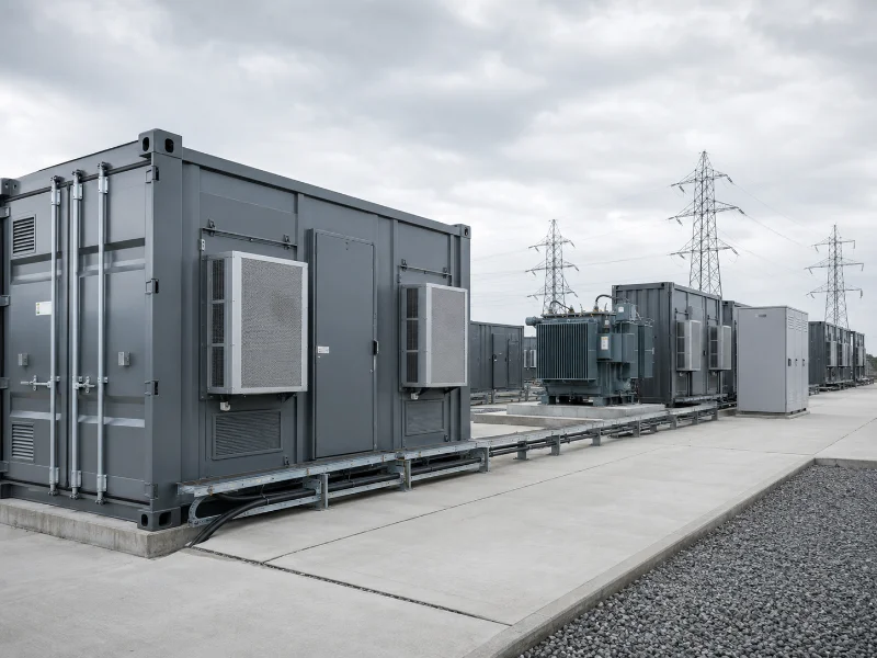
A battery energy storage system solution is an integrated package — cells, battery management system, power conversion system, energy management software, thermal management, and fire safety hardware — sized against a specific duty cycle rather than a capacity number. The configuration that fits depends on three things you can determine before contacting any supplier: your power-to-energy ratio, your site’s ambient and space constraints, and the discharge frequency your application demands. Chemistry follows from these, not the other way around. Two projects with identical megawatt-hour ratings can require different cooling architectures and different fire-protection budgets.
What a BESS Solution Includes Beyond the Batteries
A battery energy storage system solution comprises, at minimum, six subsystems whose sizing is interdependent, and on high-power or space-constrained projects the thermal limit is often what binds first. Battery modules store the charge. The battery management system tracks cell voltage, temperature, and state of charge. The power conversion system moves energy between DC storage and AC grid or load in both directions. The energy management system decides when charging and discharging happen, working against price signals, load profile, and grid conditions. Thermal management holds cells inside their operating window. Safety systems detect, contain, and suppress failure events. A full delivery scope typically adds DC protection, AC switchgear, transformer, metering, SCADA and communications, auxiliary power, gas detection, ventilation, grounding, and cybersecurity controls.
Which constraint binds first is project-specific. On other projects, interconnection capacity, transformer or PCS ratings, site layout and fire separation, noise limits, or permitting may dominate before any thermal limit is reached. What holds generally is the coupling. The PCS rating places an upper bound on how fast the pack can cycle. Realised cycling rate — also shaped by usable energy, DC voltage window, BMS current limits, and SOC and temperature derating — drives heat generation. Heat generation constrains the cooling architecture, and cooling architecture sets enclosure footprint and parasitic load.
Power and Energy Are Two Separate Specifications
Sizing a battery energy storage system requires two independent numbers, power in megawatts and energy in megawatt-hours, and confusing them produces systems correctly sized for the wrong problem. Power describes how much the system delivers at any instant. Energy describes how long it sustains that delivery. A 1 MW / 4 MWh system delivers its full rated output for roughly four hours; a 1 MW / 1 MWh system delivers the same instantaneous power for about one hour.
Both numbers need boundary conditions before they mean anything in a contract. Specify whether energy is DC nameplate or AC deliverable, whether it is nominal or usable after SOC reserve, whether it is stated at beginning of life or guaranteed at end of life, and whether round-trip efficiency includes PCS and auxiliary loads. Two quotations carrying the same MWh figure can differ materially in delivered energy once these boundaries are applied.
The ratio between power and energy — the C-rate — is a useful first-pass indicator of thermal demand, though it cannot replace cell-level resistance data and a time-resolved duty-cycle model. For systems of the same nominal energy capacity and DC voltage, cutting discharge duration from four hours to one raises current by roughly four times. Under a simplified constant-resistance model, instantaneous I²R heat-generation power rises by approximately sixteen times, while cumulative resistive heat over the full discharge rises by approximately four times, since the discharge lasts a quarter as long. Actual values depend on cell resistance, state of charge, temperature, and voltage architecture.
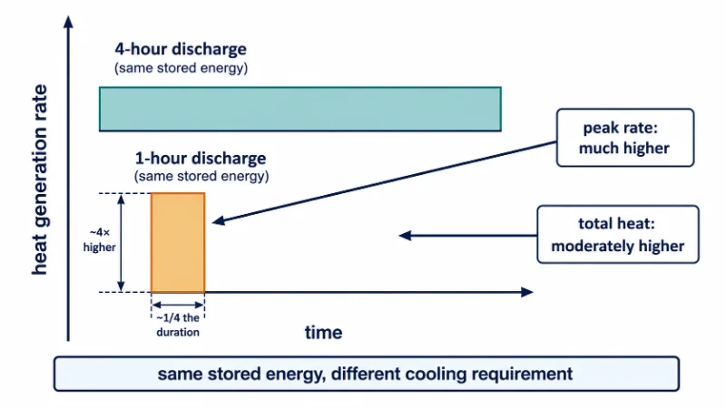
That distinction between peak power and cumulative energy is what makes duration a cooling question rather than a capacity question. A cooling system must reject the instantaneous peak, not the average. Two systems storing identical energy, one cycling in an hour and one over four, therefore present cooling loads that differ by far more than their nameplate ratings suggest. This is why frequency-regulation assets and four-hour arbitrage assets rarely share a cooling architecture even when their capacities match, and why a high-C-rate application narrows the viable set of chemistries and enclosures before any commercial preference is applied.
Where Chemistry Constrains the Decision
Battery chemistry sets the thermal and safety envelope a solution is designed around, and its practical effect on configuration is narrower than most comparison tables suggest. Lithium iron phosphate is generally more thermally stable than nickel-manganese-cobalt formulations, which affects system-level fire-test performance. Lead-acid remains serviceable where cost dominates and cycle count is low. Flow batteries decouple power from energy by scaling stack and tanks independently, at lower energy density. Sodium-based chemistries are an emerging class positioned on material abundance.
Chemistry is usually presented as the first decision, but its dominant downstream consequence is thermal and regulatory rather than electrical. A chemistry with greater intrinsic thermal stability may improve system-level fire-test performance. Separation distances and suppression requirements, however, are determined by the listed system configuration, the applicable code edition, UL 9540A test data, installation layout, and AHJ acceptance — not by chemistry alone. A chemistry selected without its thermal and code consequences priced in is a decision made twice.
Thermal Management Is Where BESS Configurations Diverge
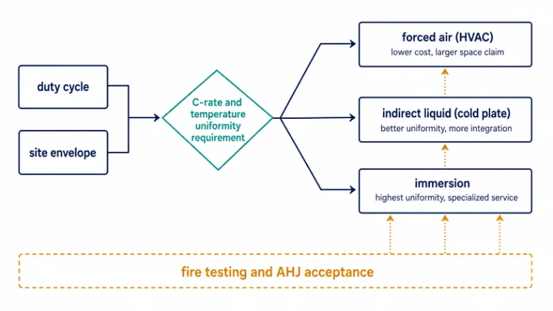
Thermal architecture is a system-level routing decision, and it is the specification most likely to be inherited unexamined from a reference design built for a different C-rate. Commercial BESS products primarily use HVAC-based air cooling or indirect liquid cooling. Immersion cooling is an emerging option where temperature uniformity or propagation resistance is the priority, though its deployment base and service ecosystem remain more limited.
| Cooling route | Suited to | Main constraint |
|---|---|---|
| Forced air (HVAC) | Low C-rate, moderate ambient, cost-sensitive sites | Air’s low heat capacity limits removal rate; gradients grow across large packs |
| Indirect liquid (cold plate) | Moderate-to-high C-rate, dense packing, wide ambient swings | Requires coolant loop, pump parasitics, leak-path engineering |
| Immersion | High C-rate, high uniformity demand, propagation-resistance priority | Fluid compatibility, weight, serviceability, limited deployment base |
The procurement consequence is what belongs in a configuration decision. Temperature non-uniformity across modules creates differences in internal resistance, available power, and ageing rate. Over time those differences increase cell imbalance, and the BMS reaches its voltage or temperature limits on the outlying modules before the pack as a whole is exhausted, which reduces usable system energy. A route that lowers average temperature while widening spread can therefore cost more usable energy than it saves in cooling load. Average-temperature specifications cannot discriminate between these three routes. Spread specifications, measured at a stated level of cell, module, or rack, can.
A note on scope. The mechanism behind that spread — heat generation sources, optimal lithium-ion operating windows, cold plate heat-transfer design, and interface material selection — is pack-level engineering covered in our guide to optimising battery pack thermal management. Where the route is already fixed and the question is hardware and simulation scope, that sits with battery pack thermal management. This article stops at which route a duty cycle and site permit.
Standards That Define the Safety Baseline
United States BESS compliance combines product standards, fire and building codes, electrical installation requirements, and project-specific AHJ conditions, and no single document covers it. UL 9540 is the safety standard for energy storage systems and equipment; systems are listed to it rather than certified by it. UL 9540A is a test method for evaluating thermal runaway fire propagation, producing empirical data rather than a pass/fail result — data that designers and authorities having jurisdiction use to set separation distances, venting, and fire control strategies. NFPA 855 is the installation standard for stationary energy storage systems, addressing barriers, suppression, monitoring, and ventilation at the site level. It carries force where a state, city, or AHJ has adopted or referenced it.
These three sit alongside the adopted IFC or NFPA 1, NEC Article 706 for electrical installation, UL 1973 for batteries in stationary applications, UL 1741 for PCS and interconnection equipment, and local interconnection requirements. Projects outside the United States work to equivalent frameworks, with the IEC 62619 and IEC 62933 series as the usual reference points. Confirm the applicable set for the destination market before configuration is fixed.
Because UL 9540A results affect how stringent NFPA 855 requirements become, a system’s test data influences site-level cost before a foundation is poured. Requesting that data is a site-cost input, not a compliance formality. The report only helps if the tested configuration matches the proposed installation. Confirm which editions apply in the target jurisdiction, since requirements differ by capacity, separation distance, and residential versus non-residential installation.
Which Variable to Confirm First
Two inputs should be settled before other specification work begins: the duty cycle (discharge duration, cycles per day, depth of discharge) and the site’s thermal and spatial envelope (ambient range, available footprint, indoor or outdoor placement).
Both are expensive or impossible to change later. Duty cycle is set by the commercial application, and the site is usually a fixed asset. Other variables retain some flexibility during concept design, but chemistry, enclosure architecture, and supplier platform should be frozen before detailed permitting, fire analysis, and balance-of-plant design, because each of those activities consumes the earlier choices as fixed inputs. Fixing a flexible variable before a fixed one produces the most common failure mode in BESS procurement: a system correctly built to a specification that no longer matches the application.
For short-duration backup-only applications with no time-of-use spread and no demand-charge exposure, a generator or UPS may well have the lower installed cost per delivered kilowatt-hour. Battery storage is worth questioning there. The honest comparison needs a lifecycle model covering outage frequency and duration, fuel and maintenance, emissions and noise constraints, response time, demand-charge savings, any grid-service or capacity revenue, and the cost of unserved load. Storage generally earns its cost where it performs several functions at once. A single-function case can still stand up, but it should be tested rather than assumed.
Parameters worth confirming in writing before comparing quotations:
| Parameter | What to confirm |
|---|---|
| Rated AC power | Continuous and overload rating |
| Usable AC energy | At BOL and guaranteed at EOL |
| Duration | At rated AC output |
| Round-trip efficiency | Test boundary and auxiliary loads |
| Availability | Definition and exclusions |
| Temperature uniformity | Measurement level: cell, module, or rack |
| Auxiliary consumption | Standby and full-load conditions |
| Degradation | Calendar and cycling assumptions |
| Fire testing | Exact tested configuration |
| Warranty | Throughput, cycles, SOC and temperature limits |
Where to Start with Your BESS Specification
Two variables carry the decision: the duty cycle the application imposes, and the thermal and spatial envelope the site provides. Fix those, and chemistry, cooling route, and enclosure follow with less guesswork. Everything downstream — degradation projections, fire-protection budget, footprint — inherits from them.
What remains project-specific is the interaction between duty cycle and local code environment, which no article resolves remotely. Where a pack’s cooling assumption is carried over from a lower-C-rate reference design without verification, the usual result is acceptable average temperatures alongside unacceptable module-to-module spread. The correction at that stage is a redesign, not a tuning exercise. Trumonytechs compares cold plate and immersion routes against a stated duty cycle rather than a nominal rating, because the routes diverge most at the operating points where nominal figures converge.
Before the next supplier conversation, assemble the discharge duration and cycles-per-day profile, peak and average power draw, the site’s annual ambient temperature range, available footprint and indoor or outdoor placement, the grid interconnection limit, and the AHJ’s current position on installation-level fire testing. With those six inputs, a supplier can size a system and price its thermal and safety scope without assumptions standing in for data.
Where This Article Stops
Three decisions sit just outside this article’s scope, each with a dedicated guide:
- Cooling loop and cold plate design — once the route is fixed, channel geometry, flow balancing, and pump sizing follow. See liquid cooling system design for EV battery and ESS thermal management.
- Thermal runaway prevention at system level — the standards section here gives compliance coordinates only; the engineering behind propagation resistance is covered in how to prevent thermal runaway in BESS.
- Installed cost ranges — this article deliberately avoids price figures, since they move with chemistry, market, and scale. Current ranges are in solar battery storage system cost.
FAQ
Does a larger MWh rating mean a longer-lasting system?
No. Capacity sets duration, not lifespan. Cycle life depends on depth of discharge, operating temperature, and C-rate — a large system cycled hard in a hot climate can degrade faster than a smaller one operated gently.
What is the difference between AC-rated and DC-rated capacity?
DC capacity is measured at the battery terminals. AC capacity is what reaches the point of connection after PCS conversion and auxiliary loads. AC deliverable energy is always lower, and the gap widens as auxiliary consumption rises, which is why cooling architecture affects the number a warranty can be written against.
Can cooling architecture be changed after installation?
Rarely without significant rework, since the route determines enclosure geometry, structural loading, and often the pack design itself.
Do all BESS installations require UL 9540A testing?
Requirements vary by capacity, separation distance, and installation type, and the applicable edition depends on jurisdiction. Confirm with the AHJ rather than assuming a blanket rule.
What should a BESS enquiry include?
Duty cycle, site ambient range, footprint and placement, interconnection limit, and the AHJ’s position on fire testing. Without these, a supplier substitutes assumptions for data, and the quotation reflects the assumptions rather than the site.
