
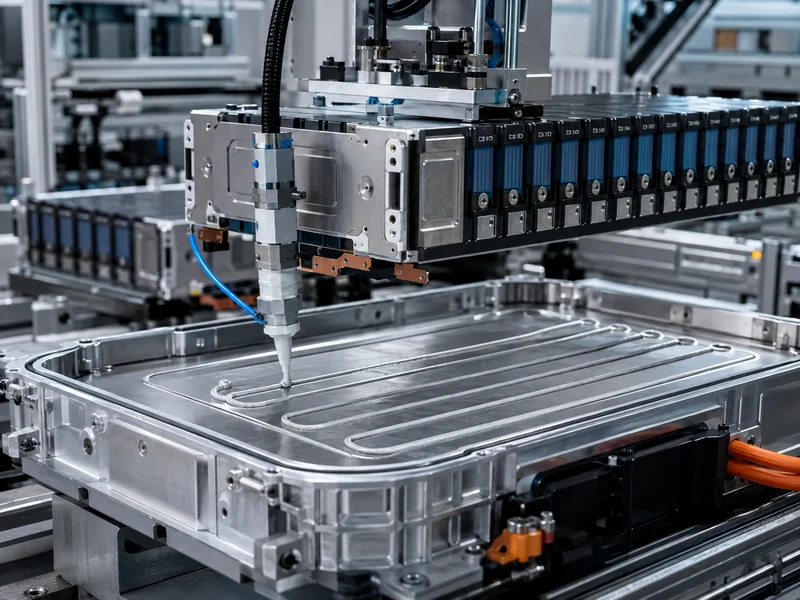
Battery module and pack assembly is a mechanical build process, not a chemistry process, and treating it that way changes how engineers plan the line. Cells arrive already finished; the value added on a module and pack line comes from how those cells are grouped, connected, held under compression, tied into a cooling path, and verified. This article walks the sequence from sorted cells to a finished pack. It pays specific attention to a step most process overviews skip: where the thermal interface materials and cold plate actually enter the build, and which assembly variables decide whether that heat path performs. The goal is a working mental model of module-level versus pack-level work, not a single vendor’s line layout.
Battery Cell, Module, and Pack: What Assembly Actually Covers
Two distinct mechanical stages make up module and pack assembly: grouping cells into modules, then integrating those modules into a pack. Separating them on paper prevents most planning mistakes. A cell is the electrochemical unit that stores energy; a module groups cells into a serviceable, structurally constrained unit; a pack integrates one or more modules with an enclosure, a cooling system, and a battery management system (BMS) into the unit that ships to the vehicle or storage cabinet. Module and pack work is mechanical assembly, while the cell itself is the output of a separate chemical process that is out of scope here.
The boundary matters because heat, force, and electrical connections are managed differently at each level. At the module level, engineers control cell-to-cell arrangement, compression, and insulation. At the pack level, they control how modules sit against a cooling structure and how the whole assembly is sealed and monitored. Readers who want the definitional line drawn cleanly can review the difference between battery module and battery pack before mapping their own process. Everything downstream in this article assumes those two stages are planned as connected but separate operations.
Cell format sets constraints before the first station is designed. Cylindrical, prismatic, and pouch cells stack, tolerate compression, and present their heat-transfer surfaces differently, so a line built around one format rarely transfers cleanly to another. The practical consequence is that stacking fixtures, end-plate loads, and the location of the thermal interface all follow from the cylindrical, prismatic, and pouch cell formats chosen for the program, not the other way around.
The Battery Module Assembly Process, Step by Step
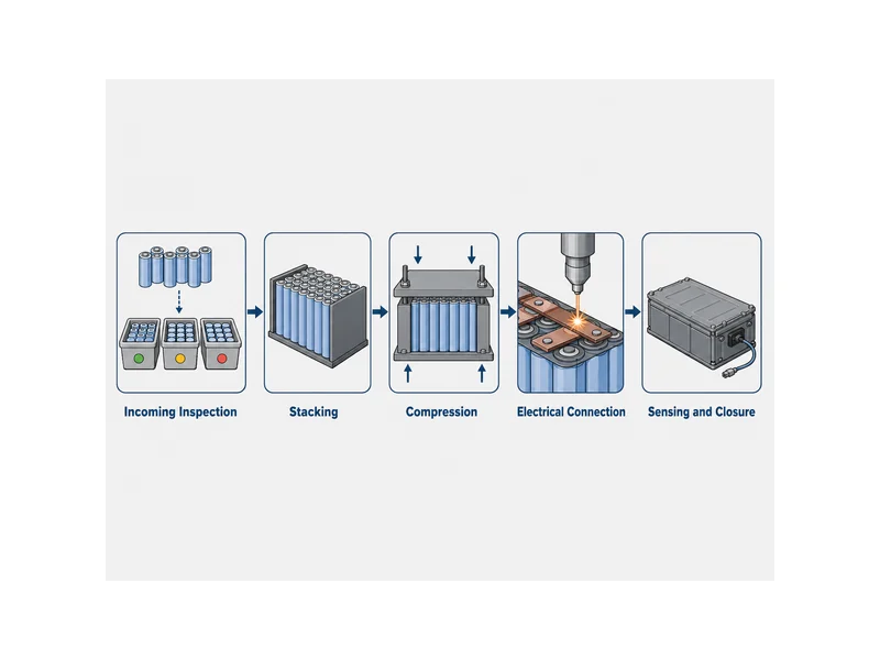
Each station on a module line adds a constraint that the next station depends on, so the build order is not arbitrary. The steps below reflect the common flow seen across module lines, generalized instead of tied to any one configuration:
- Incoming inspection and sorting: cells are checked for voltage and internal resistance, then grouped so that a module is built from cells with matched characteristics.
- Stacking: cells are arranged in the designed series and parallel pattern, with insulation and thermal barrier layers placed between or around cells as the design requires.
- Compression and end plates: the stack is held between end plates and brought to a target clamping force, then fixed with straps, tie rods, or a frame so the cells stay under controlled pressure through service life.
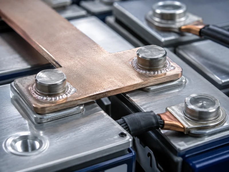
- Electrical connection: cell terminals are joined with a busbar or a wiring harness, typically with laser welding at the busbar-to-terminal joints.
- Sensing and closure: voltage and temperature sensing is connected to the module control board, and the module is closed into its case.
The line verifies polarity and orientation before any welding, because a reversed cell caught after joining is expensive to rework. Vision systems and detection tooling handle that check on automated lines. Clamping force is monitored in real time during compression so the stack reaches its designed pressure without overshoot. These are the checkpoints that separate a module that will hold tolerance from one that drifts, and they are worth designing in instead of bolting on after the first failures appear. For teams formalizing what to verify once cells become a module, battery module testing covers what changes at that level.
Compression is not a formality; it is a design variable with a service-life consequence. Cells change dimension slightly as they charge, discharge, and age, so the end-plate and strapping system has to accommodate that movement while keeping the interface surfaces flat and in contact. Too little constraint and the stack loosens; too much and the design fights normal cell breathing. The target load comes from the cell datasheet and the mechanical design, and it should be treated as a specified value, not inferred from a similar build.
Pack Assembly: Bringing Modules Into a Finished Battery Pack
System-level decisions land at pack assembly, where finished modules meet the structure, cooling, and electronics that make a usable battery. Multiple modules are placed and secured into the pack enclosure. High-voltage connections between modules are made and torqued or welded to specification. The BMS, cooling system, and safety components are then installed and connected. The pack is sealed and leak-checked, because a traction or storage pack has to keep moisture and contaminants out for years. Where the module stage manages cell-to-cell behavior, the pack stage manages module-to-system behavior, including how heat leaves the assembly.
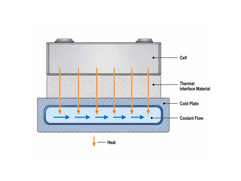
The cooling structure is a pack-level element, and its interface to the modules is defined during this stage. In most architectures the modules sit on or against a cold plate, and liquid circulating through that plate carries heat away from the cells. How well that works depends less on the plate alone and more on the quality of the contact between each module and the plate, which is why the thermal interface is treated as its own design and process problem. Teams sizing that system against real heat loads and temperature-uniformity targets can work from battery pack thermal management as they set pack-level requirements.
Alignment and connection sequencing carry real risk at the pack level. Modules must seat correctly so that high-voltage joints line up and the thermal interface achieves full contact. A module that is high on one corner leaves a gap the interface material has to fill, and a joint made under misalignment stresses the connection. Sequencing the placement, the electrical connection, and the interface application so each one is verified before the next is added keeps these faults out of the finished pack.
Where Thermal Interface Materials and Cold Plates Fit in the Assembly Sequence
Treat thermal interface placement as an afterthought and the cold plate never sees the heat it was sized to remove. The material enters at the contact between the heat-generating cells or modules and the cold plate, applied as a deliberate assembly step. It fills the microscopic and mechanical gaps between a module base or cell and the cooling surface so heat can move by conduction instead of being blocked by trapped air. In practice the material is applied to the plate or the module, the parts are brought together, and the assembly is compressed so the material wets both surfaces and reaches its designed thickness. This is the physical link in the cell-to-coolant path, and the assembly variables around it decide whether the cold plate performs.
Material choice follows from the gap, the assembly stress, and whether the joint needs to carry load or come apart for service. A conformable gap filler suits a variable or larger gap and a joint meant to be serviceable; a thermal conductive adhesive suits a bonded joint that also contributes structure, such as cell-to-plate or cell-to-pack bonding. The selection variables that matter are gap and flatness, the stress the assembly puts on the material during compression and over life, and the curing behavior of the material if it bonds. A material chosen without those numbers in hand tends to be either too stiff to fill the real gap or too weak to hold the intended contact. Engineers weighing these tradeoffs across cell formats and joint types can start from thermal interface materials for batteries and match the property set to the joint, not to a generic conductivity figure.
Application method belongs in the process plan, not just the material spec. Dispensed gap fillers and adhesives are typically applied robotically along a defined path so that volume and coverage repeat unit to unit. An interface that is starved in one region or over-applied in another changes both thermal contact and the force needed to close the assembly. The interface, the compression that sets its thickness, and the alignment that decides the gap it must fill are one linked problem; solving them together is what makes the cold plate effective. This is the point where a matched set of cooling components and interface materials, planned against the specific battery modules and pack geometry, earns its place in the build instead of being selected in isolation.
Connection, Bonding, and Testing Checkpoints Across Assembly
Every connection and bonding choice trades one property for another, so naming the variable behind each one keeps the decision out of habit. Busbars suit higher-current, more rigid module layouts and lend themselves to laser welding; wiring harnesses suit lower-current sensing and layouts that need flexibility. On the mechanical side, adhesive bonding can replace or reduce mechanical fasteners, cut weight, and remove hardware, but it introduces cure time and surface-preparation steps into the line; mechanical fastening keeps joints serviceable at the cost of parts and mass. Current, serviceability, and end-of-life disassembly drive that choice, which belongs in design, not on the line.
Testing runs across both stages instead of waiting for the end, because a fault is cheapest to catch at the station that created it. Incoming resistance and voltage sorting screens cells before they are committed to a module; polarity and vision checks confirm orientation before welding; post-weld inspection confirms joint quality before the module is closed; and the finished pack is leak-checked and functionally verified before it ships. Traceability through a manufacturing execution system ties each measurement to a specific unit, which is what lets a later field question be traced back to the station and parameter that produced it. Skipping any of these checkpoints does not remove the fault; it just moves the discovery to a more expensive point downstream.
How Cell-to-Pack Designs Change the Assembly Sequence
Cell-to-pack designs remove the module tier. That change relocates where the interface and the compression live; it does not eliminate them. In a traditional module-then-pack build, cells are constrained and cooled at the module level, then modules are interfaced to the pack cooling structure, so the heat path crosses two interfaces. In cell-to-pack, cells are integrated directly into the pack structure, which can reduce the interface stack so that one layer sits directly between the cells and the cold plate. Fewer parts and one interface can improve packaging and heat transfer, but the compression, alignment, and interface control that a module used to provide now have to be managed at the pack level.
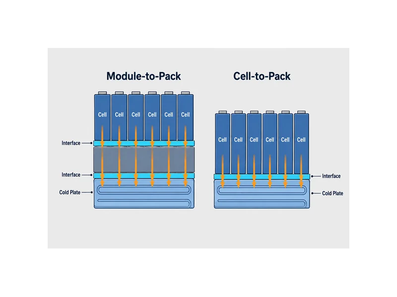
The practical effect is that assembly discipline moves; it does not disappear. The same variables that governed a module (matched cells, controlled clamping, a flat and fully wetted interface, verified connections) still decide performance, but they are now enforced during pack integration where the parts are larger and harder to rework. Teams evaluating cell-to-pack should plan the interface application and compression control at the pack line from the start, because the tier that used to absorb that work is no longer there to catch it.
Conclusion
Battery module and pack assembly breaks into two linked mechanical stages, and one step inside them carries more weight than its size suggests: the thermal interface. Module assembly earns its result through cell sorting, controlled compression, and verified connections; pack assembly earns its result through alignment, sealing, and how cleanly the modules meet the cooling structure. The point in the sequence that quietly decides whether a pack holds temperature is the contact between the cells or modules and the cold plate, and that contact is governed by gap, flatness, assembly stress, and the material chosen to bridge it. Plan the interface material and the cold plate against the actual cell format and pack geometry, verify the gap and the wetted contact as a real checkpoint, and the rest of the cooling design has something to work with. When the cooling components and interface materials are matched to the specific build instead of selected in isolation, we find the assembly line spends far less time chasing thermal problems that were designed in upstream.
FAQ
Where does the thermal interface material go between the module and the cold plate during pack assembly?
The interface material goes at the physical contact between the module base (or cells) and the cold plate, and it is applied as a defined pack-assembly step. The material is dispensed onto the plate or the module, the parts are brought together, and the joint is compressed so the material fills the gap and wets both surfaces to its designed thickness. That wetted contact is what lets heat conduct into the plate instead of stalling at an air gap.
Do I need a gap filler or a thermal conductive adhesive for cell-to-plate bonding?
Choose based on whether the joint has to carry structure and whether it must be serviceable. A gap filler suits a serviceable joint and a variable or larger gap where you want conduction without bonding; a thermal conductive adhesive suits a joint that also contributes structural strength, such as cell-to-plate or cell-to-pack bonding. Decide from the gap, the assembly stress, and the curing and serviceability needs, not from conductivity alone.
What’s the difference between module assembly and pack assembly steps?
Module assembly builds cells into a compressed, connected, serviceable unit; pack assembly integrates those modules with the enclosure, cooling system, and BMS into a finished pack. Module work manages cell-to-cell arrangement, compression, and insulation, while pack work manages module alignment, high-voltage connection, cooling contact, sealing, and system-level testing.
At which assembly step is the cold plate integrated into the battery pack?
The cold plate is integrated during pack assembly, when modules are placed and secured into the enclosure. Its interface to the modules is defined at that stage through the thermal interface material and the compression that sets the contact, so plate integration and interface application are planned together, not as separate operations.
How does cell-to-pack change where TIM is applied?
Cell-to-pack removes the module tier, so the interface can reduce to a single layer applied directly between the cells and the cold plate at the pack line. The interface still has to be applied, compressed, and verified; that control simply moves from the module stage to pack integration, where the parts are larger and harder to rework.
Further Reading
- RWTH Aachen PEM — Battery Module and Pack Assembly Process — university research chair reference on the module and pack assembly sequence; supports the module-versus-pack process boundary used throughout this article.
- IDTechEx — Reducing and Eliminating Thermal Interface Materials in EV Batteries — research-analyst article on cell-to-pack designs and TIM reduction; supports the section on how cell-to-pack changes where the interface is applied.
Related Articles
- Phase Change Materials For Thermal Energy Storage — for readers comparing the liquid cold-plate path to phase-change approaches for storing and moving battery heat.
- What Is Potting In Electronics? — explains the encapsulation compounds that protect an assembled pack from shock, vibration, and moisture, next to the sealing step in pack assembly.
- What Is The Purpose Of The Cooling Plate? — details how a cold plate draws heat from mounted modules, the component the thermal interface has to feed during pack integration.
- EV vs ESS Battery: Key Differences & Thermal Management — compares how EV and ESS packs differ in design and cooling strategy, useful when the same assembly line serves both.
- What Is an Energy Cell? Battery Engineering Definition, Design, and Thermal Management — defines energy-type cells and what their structure means for interface-material selection in a pack program.
