
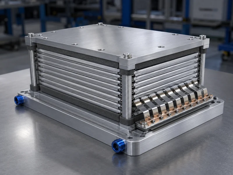
A pouch cell battery module is the structure that turns soft, foil-clad pouch cells into a stiff, connected, thermally managed building block for a larger pack. Because the pouch format trades a rigid metal can for a thin aluminum-laminate envelope, the module — not the cell — has to supply mechanical support, control swelling, route heat out, and make the electrical connections. That moves most of the hard engineering from the cell to the module. The sections below cover how a pouch cell module is built, why compression and swelling drive its mechanical design, and how heat moves from the cell face to the coolant. Pouch modules sit inside the wider family of battery modules, but their soft cell walls make the module-level constraints distinct from prismatic or cylindrical designs.
What a Pouch Cell Battery Module Is
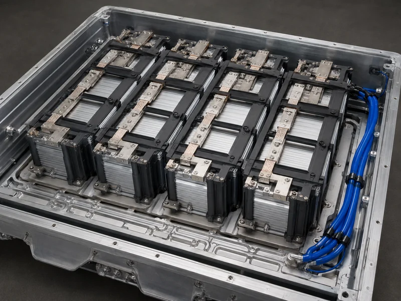
A pouch cell module gathers pouch cells under controlled pressure inside a frame, wires them in series and parallel, and couples the stack to a cooling surface. Rigid end plates or a housing carry the stack, an insulation layer separates the outermost cell from metal, and compression pads or plates keep each cell face loaded. The pouch itself is a sealed aluminum-laminate envelope holding the electrode stack and electrolyte, with flat foil tabs exiting one or both ends to carry current.
Engineers describe the build in layers, and the naming matters when you size a pack. Individual cells are first grouped into a parallel unit — variously called a parallel assembly, P-set, super-cell, or sub-module. That unit is put in series to form a module, and modules combine into a pack. Fixing the difference between a battery module and a battery pack early avoids confusion when you later assign cooling, sensing, and structural duties to the correct level.
Because pouch tabs are thin and flat, the module’s connection scheme is part of its structural design, not an afterthought. Tabs are joined tab-to-tab or tab-to-busbar, usually by ultrasonic bonding or laser welding. The flat geometry gives a large contact face but little mechanical strength, so the busbar and frame have to carry loads the tabs cannot. Sound battery module design treats the tabs, busbars, compression, and cooling as one coupled system.
Pouch, Prismatic, and Cylindrical Formats at the Module Level
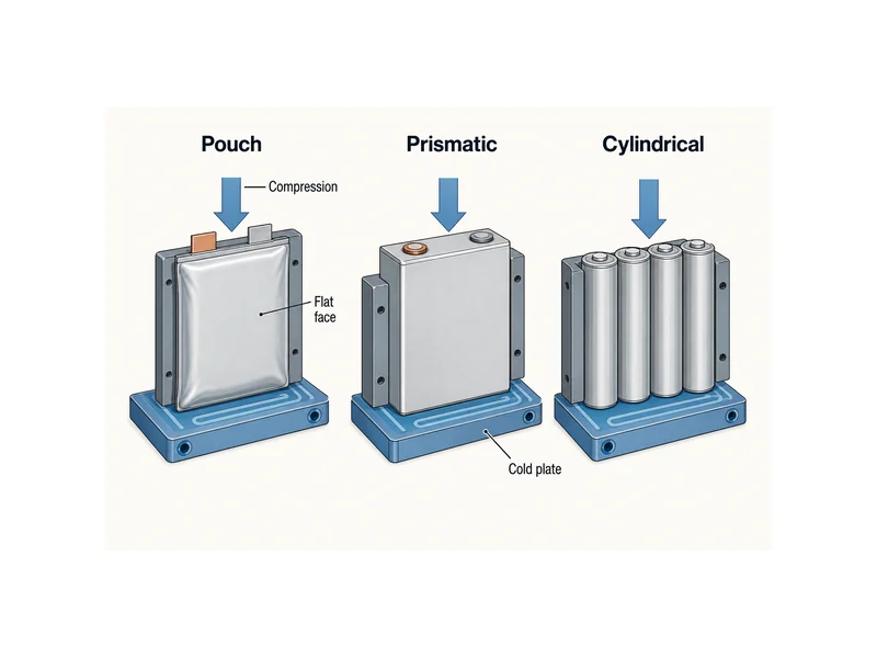
The cell format decides how much work the module has to do, and pouch shifts the most work onto the module. Cylindrical and prismatic cells bring their own rigid cans, so their modules mostly locate and connect finished cells. Pouch cells arrive soft, so their module supplies the stiffness, the compression, and the flat thermal path that a can would otherwise provide. That is the trade-off behind the pouch format’s higher cell-level energy density: less packaging mass in the cell, more structural and thermal duty in the module.
Comparing the three formats on the jobs the module inherits makes the choice clearer before a pack architecture is committed:
| Dimension | Pouch | Prismatic | Cylindrical |
|---|---|---|---|
| Cell casing | Soft aluminum-laminate pouch | Rigid rectangular can | Rigid metal tube |
| Module’s mechanical duty | High — supplies stiffness and holds swelling | Moderate — locates rigid cans | Low — cans are self-supporting |
| Cooling interface | Large flat face, needs interface material to a plate | Flat can wall or base | Curved surface, limited flat contact |
| Swelling handling | Compression is designed in | Contained by the can | Contained by the can |
Choosing among the formats is a module-level decision as much as a cell one. Cylindrical, prismatic, and pouch EV battery module types change assembly and cooling in different ways. At the module level, the pouch’s flat, compressible face is both its main advantage for heat transfer and the reason it needs external support.
Swelling and Compression in Module Assembly
Compression defines the mechanical design of a pouch cell module, because the cells swell and have to be held to survive. Pouch cells breathe with state of charge and expand slowly over life as gas and material changes accumulate inside the sealed pouch. Without external pressure the internal layers can separate, which accelerates aging and drives non-uniform wear. Modules therefore load each cell face through compression pads, foam, or sprung end plates, sized to hold the stack without crushing it.
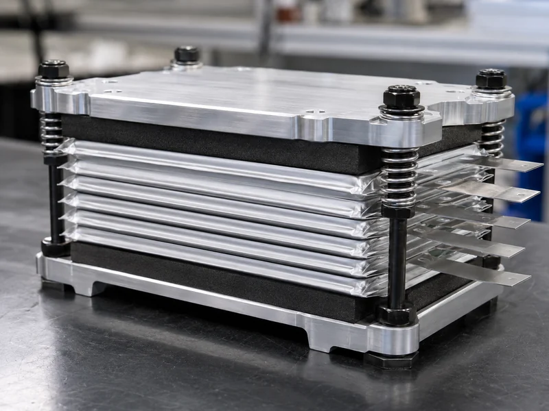
How much pressure to apply, and when, is a trade-off with no fixed number. Applying compression early in assembly limits how far the stack can grow later, while too much initial pressure on a stiff module can push pressure higher as the cells expand and speed degradation. The workable window depends on cell chemistry, format, and frame stiffness, so module builders validate compression against the specific cell rather than copying a value from another design.
The pressure level and its timing are locked in during assembly, which is why compression is designed alongside the stacking and joining sequence. The battery module and pack assembly process sets the order in which cells are stacked, compressed, and connected, and that order decides whether swelling is contained from the first cell or fought later.
The Cell-to-Coolant Heat Path
Heat leaves a pouch cell through its large flat faces. The module’s job is to give that heat a low-resistance path to a coolant. The flat face is an advantage — it presents a high surface area for cooling — but the soft, slightly uneven pouch surface does not mate cleanly to a rigid cold plate. A thermal interface material fills that gap, displacing insulating air so heat conducts from the cell into the cooling structure instead of stalling at the joint.
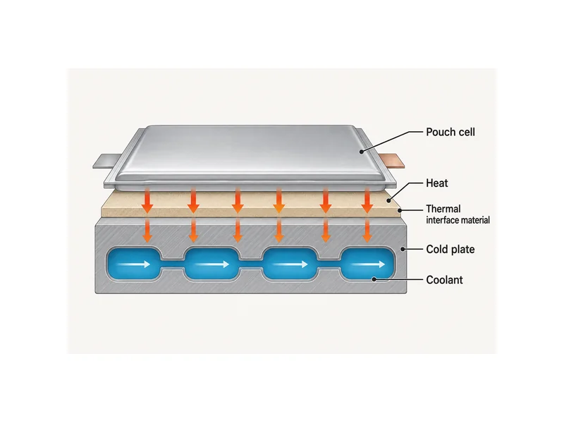
Selecting the interface material is a decision about gap, assembly stress, and how the cell is held, not just about conductivity. The right thermal interface material for a battery has to fill the real gap between the flexible cell and the plate, tolerate the compression the module already applies, and keep contact as the cell breathes. A gap filler that is too stiff adds assembly stress; one that is too thin leaves voids on an uneven face.
Where the cold plate sits sets the cooling ceiling for the whole module. Two integration patterns are common. A cold plate on the side or bottom of the stack serves many cells with one plate and simplifies the build; plates between cells cool harder but multiply parts and are difficult to scale. Either way, the aim is to hold every cell inside the band where lithium-ion cells perform and age best — commonly cited around 15–45 °C. The cooling also has to keep cells within a few degrees of each other, since EV battery cooling that leaves one cell hotter drives uneven aging across the module.
The cooling components and interface materials therefore have to move together as one selection; choosing them separately leaves the interface mismatched to the plate. Trumonytechs supplies liquid cold plates and thermal interface materials meant to work together along this cell-to-coolant path, so the gap filler suits the plate and the compression the pouch module already carries. Which specific material and plate fit a given module still depends on the cell’s gap, flatness, and heat load, and should be confirmed against those numbers rather than assumed.
Where Pouch Cell Modules Fit
Pouch cell modules fit applications that reward high cell-level energy density and a flat cooling face, which is why they are common in EV and stationary energy-storage packs. Their soft cells rule them out of designs that ask the cell to carry structural load, such as cell-to-pack layouts where the cell wall doubles as pack structure. Within a conventional module-and-pack architecture, the pouch format concentrates the engineering effort on compression, the thermal interface, and cooling — the same three constraints that shape the rest of this article.
Safety scope also follows from the soft format, because a pouch can be punctured or can vent gas if it is abused. Cell and pack safety are governed by published standards such as the IEC 62133 series and UL 1642 and UL 2054, which set the test protocols, not the module geometry. The module’s own contribution is holding the cells stable, cool, and evenly loaded so those failure modes are less likely to start.
What the Module, Not the Cell, Has to Solve
A pouch cell battery module is best read as the part that supplies everything the soft cell gives up: stiffness, compression against swelling, and a clean path from the cell face to the coolant. Format choice, compression window, interface material, and cold-plate placement are not separate specs but one coupled decision, because changing the compression changes the thermal contact, and changing the cooling layout changes how evenly the stack ages. The part most often misread is treating the thermal interface material and cold plate as independent picks — at the module level they only work as a matched pair sized to the same gap, stress, and heat load. Engineers integrating pouch cells can start by fixing the cell’s gap, flatness, and heat load, then choosing the compression and the interface-and-plate combination against those numbers.
FAQ
Do pouch cells need compression in a battery module?
Yes — pouch cells need controlled compression because they swell with use and their soft layers can separate without it. Modules apply that pressure through pads, foam, or sprung end plates sized to hold the stack without crushing it, and how much to apply is set by the cell and frame, not a universal figure.
Why do pouch cells swell, and how does the module handle it?
Pouch cells swell because gas and material changes build up inside the sealed pouch, and the effect grows over life and near full charge. The module handles it by compressing each cell face and by applying that pressure early in assembly, which limits how far the stack can grow later.
How is heat pulled out of a pouch cell module?
Heat leaves through the cell’s large flat faces into a thermal interface material and then a cold plate, placed on the side or bottom of the stack or between cells. The interface material matters because the soft, uneven pouch face will not conduct heat into a rigid plate across an air gap on its own.
What thermal interface material goes between pouch cells and the cold plate?
A gap-filling thermal interface material — typically a gap filler or thermal pad — bridges the soft pouch face and the cold plate so heat crosses the joint that trapped air would otherwise block. The choice follows from the cell’s real gap, its flatness, and the compression already in the module, so it is matched to the specific plate and cell, not chosen on conductivity alone.
Pouch, prismatic, or cylindrical — which is easiest to cool at the module level?
Pouch cells offer the most cooling-friendly geometry because their large flat face gives a high surface area for heat transfer, but that face has to be matched to the cold plate with an interface material to realize it. Prismatic and cylindrical cells bring rigid cans that are easier to locate but present less flat area per cell to the cooling surface.
Further Reading
- The Evolution of Pouch Cell Battery Pack Designs (Laserax) — manufacturer technical article. Supports the format trade-offs and the cold-plate integration discussion.
- For EV Battery Packs, Does the Shape Matter? (Recurrent Auto) — industry technical resource. Supports the pouch-versus-prismatic-versus-cylindrical comparison and the structural-limitation note.
Related Articles
- What Is an Energy Cell? — Explains how an energy-type cell differs structurally and thermally from a power cell, and what that means for module thermal management and interface-material choice.
- Why Battery Protection Matters Electric Vehicle — Covers why cell, module, and battery-management protection matter for EV battery life and safety.
- Thermal Pad Uses — Shows how to match a thermal pad to a component by through-plane conductivity, conformability, and bondline thickness.
- Ceramic Thermal Paste — Explains where ceramic-filled thermal grease fits for battery gap filling and where it does not.
