

Thermal interface material thickness sets how much heat crosses the joint between a cell or module and its cold plate. In a battery pack it is a design variable, not a leftover assembly dimension. A thinner interface lowers thermal resistance. But the real gap, the filler particles, the compression window, and the way cells move over their life all set a practical floor on how thin you can go. Getting that number right is central to specifying high-performance thermal interfaces along the cell-to-coolant heat path. There, a fraction of a millimeter changes both the temperature the cells run at and the stress the assembly carries.
Choosing thickness means choosing the TIM class at the same time: the gap decides which class is feasible, and the class sets the thickness range you can work in. This article covers the physics that ties thickness to heat transfer, why thinner is not automatically better, how to match thickness to the assembly gap, and how compression and cell swelling constrain the choice. It does not cover TIM chemistry formulation or the structural bonding of pack components, which follow their own selection rules.
Why Thickness Drives Heat Transfer Across the Interface
Across a thermal interface, resistance to heat flow rises roughly in proportion to bond line thickness. Every added fraction of a millimeter is extra resistance the cooling system has to pull heat through. Industry technical guidance frames this as a near-inverse relationship: halving the bond line thickness approximately doubles the effective heat transfer rate when the other variables hold constant. For a pack engineer, that is why a nominally small change in pad thickness can move a cell’s steady-state temperature by a meaningful margin.
Thickness never acts alone. The material’s thermal conductivity and the contact resistance at each face share the budget. A thicker interface can still perform if its conductivity is high enough to offset the added path length. That is why comparing a pad’s gap pad thermal conductivity against the thickness it needs to fill matters more than either number in isolation. The practical check is to estimate interface resistance as thickness divided by conductivity, add the contact terms, then confirm the total lands within the pack’s temperature-uniformity target before committing to a thickness.
Why a Thinner Bond Line Is Not Always Better
A bond line can be too thin. Below the filler’s particle size or the surfaces’ flatness, the material either fails to fill the gap or gets squeezed into voids that trap air. The minimum achievable thickness is set largely by the largest filler particles: the joint cannot be pressed much below that size no matter how hard it is clamped. The actual floor comes from the chosen material’s particle-size distribution, the surface finish, and the clamping conditions. Pushing past that floor does not buy lower resistance; it buys uneven contact.
Trapped air is the specific failure to avoid. Air conducts heat at only about 0.02 W/m·K, so any void becomes a local insulator that erases the benefit of going thin. Uneven surfaces, warped cold plates, and tolerance stack-up all argue for a bond line thick enough to conform, not the thinnest one a datasheet allows. The verification action is to set the minimum thickness from the worst-case surface irregularity and filler size first, then treat that as the floor the design cannot drop under.
Matching Thickness to the Assembly Gap
Start thickness selection from the pack’s real gap, not from a target conductivity. The nominal clearance between cell or module and cold plate, plus its tolerance stack-up, decides which TIM class and thickness are even feasible. Thin, well-controlled joints suit grease, phase change materials, and thin films. Larger and more variable gaps call for pads, dispensed gap fillers, or two-part liquids. Choosing a class that cannot span the gap is the most common way thickness selection goes wrong before a single number is picked.
The measured gap range is what eliminates the classes that cannot fit before any number is chosen, so it sets the shortlist and the thickness follows. The table below maps the common TIM classes to the gap ranges they typically serve. Ranges are approximate and depend on the specific product, but the ordering by gap is consistent across the field.
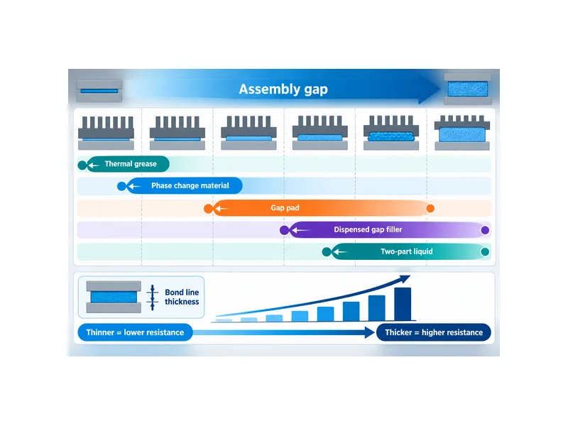
| TIM class | Bond line / gap it typically suits | Typical thermal conductivity | Pack integration note |
|---|---|---|---|
| Thermal grease / paste | Thin joints, often below ~0.1 mm | Low single digits W/m·K | Needs flat, rigid mating faces; can pump out under cycling |
| Phase change material | Thin joints, tens of microns | Low-to-mid single digits W/m·K | Flows at temperature to wet the surface; needs clamping force |
| Thermal gap pad | Roughly 0.5–5 mm | Commonly ~1 to a few W/m·K, some higher | Compliant; handles tolerance and slight movement |
| Dispensed gap filler | Gaps above ~0.5 mm, variable | A few W/m·K | Conforms to complex geometry; automates well |
| Two-part liquid / gel | Thick or variable gaps, ~0.5–2.5 mm | Up to about 10 W/m·K for some gels | Suits vibration-heavy automotive use; dispensed in any pattern |
For gaps that vary across a large module, a dispensed liquid thermal interface material can hold a more uniform bond line than a single fixed pad thickness. It settles to the local clearance instead of forcing one value everywhere. Whichever class fits, the thickness should be the smallest value that reliably fills the measured gap across its tolerance—not a round number chosen for convenience.
Compression, Assembly Stress, and Cell Movement
Specify pad thickness against the compressed state, not the free state. A gap pad only reaches its rated thermal resistance once it is squeezed into its working window, commonly around 20% to 40% of its free thickness depending on the material. Too little compression leaves an insulating air layer at the interface. Too much either crushes the cell or overloads tabs and welds. Because those two failures sit at opposite ends of the tolerance band, the pad thickness has to hold the window at each end, not at a single nominal gap.
The compression check therefore runs at both ends of the tolerance band. Run the largest assembly gap (maximum clearance plus tolerance) against the pad’s low-compression edge to confirm it still seats against both faces and keeps continuous contact. Then run the smallest gap, with cell swelling and the full clamping path stacked on top, against the high-compression edge to confirm the pad does not over-compress or drive load into the cell, tabs, and welds. A thickness that passes only the mid-gap case can still fall out of contact at the loose end or overload the cell at the tight end. Keep any geometry here to general clearance-minus-swelling relationships, and read the compression limits from each material’s datasheet and the project’s load budget.
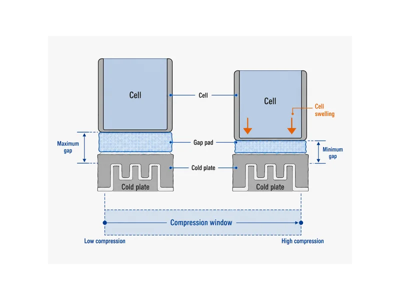
Cell movement makes this a moving target in a battery pack, which is why a thermal pad sized only for the as-built gap can fall out of its window in service. Prismatic cells swell on the order of a few percent across their state-of-charge range, with a further slow, largely irreversible growth over service life. The compression window has to absorb that expansion without losing contact or overstressing the cell. Materials also take a compression set, thinning permanently over time, so a pad that starts mid-window can drift toward the low-compression edge. The verification action is to check that both the swollen worst case and the crept end-of-life case still keep the interface compressed enough to conduct.
Verifying Thickness Holds Up Over Service Life
Confirm that the chosen thickness still performs after aging, not only at build. Interface resistance drifts as materials take a compression set, dry out, or pump out under thermal cycling. A thickness that meets the temperature target on day one can quietly lose margin once the pad has thinned or a grease line has migrated. Long-term behavior, not the datasheet’s nominal value, is what determines whether the pack stays within its thermal limits.
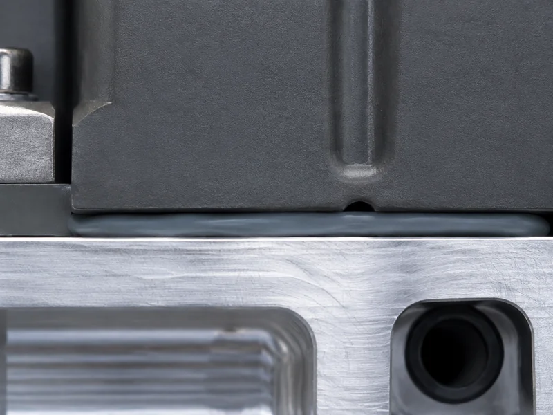
Controlling and measuring the bond line is what makes this checkable. Filler particles act as natural spacers under adequate clamping pressure, shims or hard stops can fix a minimum, and cured assemblies can be confirmed with calipers or cross-section. On the aging side, compression set is commonly tested to ASTM D395, and some pack specifications cap how much thermal resistance may rise after a defined number of cycles. The practical rule is to qualify the interface at its aged, compressed, swollen worst case, then specify the thickness that survives that state.
The Bottom Line on Thickness
For a battery pack, fix the gap before the material: measure the nominal cell-to-cold-plate clearance and its tolerance stack-up, then choose the thinnest TIM class that reliably fills that gap and still lands in its compression window across the cell’s swelling range. Thickness is not a single number to minimize but a range that has to stay valid from build through end of life. The ordering—gap first, class second, thickness last—keeps the choice from collapsing into a datasheet comparison. Because the pad and the cold plate share one heat path, the thickness should be specified together with the cooling surface it mates to. Trumonytechs supplies both the interface materials and the matched liquid-cooling cold plates that sit on that cell-to-coolant path, so the interface thickness can be set against the actual cooling surface, not in isolation. That is a product-fit point; the gap-first thickness logic above holds whatever supplier you use. The thickness worth committing to is the one that still conducts in the compressed, swollen state at the project’s aged, end-of-life condition, not the smallest value the material could theoretically reach.
FAQ
How thick should a thermal pad be for a 1 mm gap?
Size the pad slightly thicker than the nominal 1 mm gap so it compresses into its working window once clamped, rather than choosing exactly 1 mm. The right free thickness depends on the pad’s recommended compression range and the gap’s tolerance, so the target is a compressed thickness near 1 mm with the material still inside its rated compression, not a fixed off-the-shelf number.
Is a thinner thermal interface material always better?
Thinner lowers thermal resistance only until it drops below the filler particle size or the surfaces’ flatness, after which it traps air voids that conduct heat poorly. The best thickness is the smallest one that still fills the real gap uniformly and stays within the material’s compression window, not the smallest one physically possible.
Should I use a gap filler or thermal grease for a 2 mm gap?
Use a gap filler or pad for a 2 mm gap; thermal grease and phase change materials are meant for thin joints, often well under a few tenths of a millimeter. A 2 mm clearance is squarely in gap-filler and pad territory, where a compliant material can span the gap and absorb tolerance without pumping out.
How much should a gap pad compress when clamped in a battery pack?
Aim for the compression window the pad is rated for, commonly on the order of 20% to 40% of its free thickness, so it seats against both faces without crushing the cell. The exact figure varies by material, so specify pad thickness against the clamping path and worst-case gap so the compressed state falls inside that range.
Do I need to account for cell swelling when choosing pad thickness?
Yes—prismatic cells expand by a few percent over state of charge and service life, so the pad thickness and its compression window must tolerate that growth. Choose a thickness that keeps the interface conducting at the swollen worst case while avoiding overload of the cell, and re-check it against end-of-life compression set.
Why does my thermal interface trap air voids, and how do I avoid them?
Air voids form when the bond line is pressed below the filler particle size or when the mating surfaces are too uneven for the material to conform, so trapped air replaces contact. Work through it in order: check that the pad or filler is thick enough to clear the largest filler particles, that the surfaces and cold plate are flat enough to wet fully, that coverage spans the whole footprint, and that the clamping force actually seats the material across its rated compression. Fixing the thinnest or least-flat spot usually clears the void, rather than adding pressure everywhere.
Further Reading
- Guide to Choosing the Right Thermal Interface Material by Type — Manufacturer selection guide. Supports the bond-line-thickness ranges that differ by TIM type.
- Thermal Interface Materials for Long-Term Reliability in Battery Systems — Industry battery-systems article. Supports the compression, cell-swelling and aging constraints on pad thickness over service life.
Related Articles
- Thermal Gel vs Thermal Paste — Weighs two dispensable interface materials by conductivity and use, useful when a thin joint could take either gel or paste.
- Thermal Gel vs. Thermal Pad: Key Differences Explained — Explains how a dispensed gel and a fixed pad fill the same gap differently, which helps when the class is still undecided.
- Silicone Thermal Pad Advantages, Limitations & Selection Guide — Covers silicone pad strengths and failure modes like oil bleed and outgassing, extending the pad aging limits discussed here.
- Thermal Paste Alternative: Engineered Options and How to Choose — Lists engineered replacements for paste and the factors behind the choice, broadening the class-by-gap decision.
- What are Thermal Pads? — Defines thermal pad types and applications, a grounding read before sizing pad thickness for a pack.