
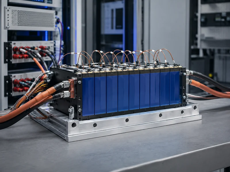
Battery module testing verifies a group of cells once they are joined into a single mechanical and electrical assembly. The point most teams underestimate is how much the assembly itself adds to the test list. A cell test tells you how a cell behaves in isolation. A module test has to account for more: busbars, welded or bolted interconnects, contact pressure against cooling surfaces, and the temperature spread across cells. None of that shows up at the cell bench. Whether a line builds standardized packs or custom battery modules, those assembly-level variables are why module data cannot be extrapolated from cell data. This article maps what module testing covers, how it differs from cell and pack testing, which standards apply, and where thermal-management design decisions surface in the results.
What Battery Module Testing Covers
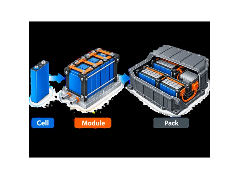
Battery module testing sits in the middle of a three-level sequence—cell, module, pack—and each level answers a different question. Cell testing characterizes the electrochemistry: capacity, resistance, and how a single cell ages. Module testing asks whether a defined group of those cells still performs as expected after they are interconnected, clamped, and thermally coupled. Pack testing then adds the enclosure, the full battery management system, contactors, and system-level thermal and safety behavior. Confusing these levels is common. The practical consequence is a test program that either repeats cell work or skips module-specific checks. That is why the difference between a battery module and a battery pack is worth settling before a test plan is written.
Most module programs group their checks into performance, safety, and durability. Performance covers capacity, energy, power, internal resistance, and how those hold up across temperature and state of charge. Safety covers the response to abuse and fault conditions—short circuit, overcharge, and the way heat moves if one cell fails. Durability covers cycling and calendar behavior, plus the mechanical and environmental stresses a module sees in service. The categories overlap, but keeping them distinct helps a team decide which tests are one-time design validation and which belong on a production line.
What Changes Once Cells Become a Module
The defining trait of module testing is that assembly introduces losses and asymmetries that no cell test can predict. Busbar resistance, weld or fastener quality, and interconnect topology all add series resistance and create uneven current paths. As a result, a module can show higher effective internal resistance and localized heating even when every cell passed its own screening. Weld quality in particular is a module-level failure mode: a marginal joint can pass at low current and then heat up or open under load. That behavior is why connection integrity and resistance mapping belong on the core module checklist.

Contact pressure and thermal coupling are the other variables that only exist after assembly. Three things decide whether heat actually leaves the cells at the rate the design assumed: how cells are held, how flat the cooling interface is, and how consistently the thermal interface material fills the gap. Cell format drives this too. Cylindrical, prismatic, and pouch cells present very different contact geometries and swelling behavior, so the EV battery module type changes both the mechanical fixturing and the thermal test setup. Sound battery module design tries to control these variables up front, but testing is what confirms the as-built module matches the intent.
The Four Test Categories for Battery Modules
Module test programs are usually organized into four categories, and reading a supplier’s or lab’s scope against these four is a quick way to spot gaps. Each category targets a different class of risk, and a complete program touches all four at least during design validation.
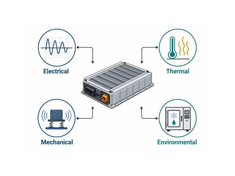
Electrical
Electrical testing establishes the module’s baseline performance and its interconnect health. Typical measurements include capacity and energy under controlled charge and discharge, internal resistance by DC pulse (DCIR) and AC methods (ACIR), and impedance behavior via electrochemical impedance spectroscopy (EIS). At the module level these methods also expose connection problems—an unexpected resistance rise usually traces to a weld, busbar, or terminal connection. Voltage sensing accuracy matters here, since small errors propagate across many series elements.
Thermal
Thermal testing checks how the module heats up, sheds heat, and behaves when a fault releases energy. It spans steady-state and transient temperature rise under load, temperature uniformity across cells, and thermal cycling. On the safety side it covers thermal runaway and propagation behavior—whether heat from one failing cell spreads to its neighbors. Propagation testing is inherently module-level because it depends on cell spacing, interconnects, and the cooling path, none of which exist at the cell bench.
Mechanical
Mechanical testing confirms the module survives the physical environment of a vehicle or installation. Common checks include vibration and mechanical shock, and, for abuse validation, crush and penetration. The module-specific concern is that vibration can loosen interconnects or fatigue welds over time. Mechanical tests are therefore often paired with a resistance or capacity check before and after, to catch degradation that a visual inspection would miss.
Environmental
Environmental testing exposes the module to the climate range and transport conditions it must tolerate. This typically includes high- and low-temperature operation, humidity, thermal shock, and altitude, and for transport, the sequence defined in the UN Manual of Tests and Criteria. Environmental chambers make these tests repeatable, but the meaningful result is usually electrical performance measured before and after exposure, not the exposure itself.
Standards That Apply to Battery Module Testing
No single standard governs battery module testing; the applicable set depends on the application—automotive, stationary storage, or transport—and often several apply at once. Instead of memorizing clause numbers, it helps to know what each body governs. IEC 62660 addresses performance and reliability testing of lithium-ion cells for electric road vehicles, with parts that extend to reliability and abuse. UL 2580 covers batteries for use in electric vehicles at the system level. SAE J2464 is the reference many teams cite for abuse and safety testing, and SAE J2380 for vibration. For transport, UN 38.3 defines the test sequence a lithium battery must pass before it can ship.
Fire and propagation behavior have their own framework. One worth knowing is UL 9540A, which structures energy-storage fire testing as an escalating sequence: cell, then module, then unit, then installation. Results at one level inform the next. That escalation is exactly why module-level thermal-runaway data matters: it is the input to unit- and installation-level fire assessment, not a standalone number. Automotive programs may also reference regional regulations such as UNECE R100 or national requirements, and stationary storage often invokes additional IEC safety standards. Confirm the current edition and the exact test conditions against the published standard before committing a plan, because editions and scopes change.
Where Thermal-Management Design Shows Up in Module Testing
Thermal test results are often a direct readout of thermal-management design choices, which is why the two should be planned together. Temperature uniformity, peak temperature under load, and the temperature delta between the hottest and coolest cell all depend on the cooling architecture and how well it contacts the cells. A cold-plate layout that looks adequate on paper can still show a wide temperature spread if the interface is uneven or the contact pressure is inconsistent across the module.
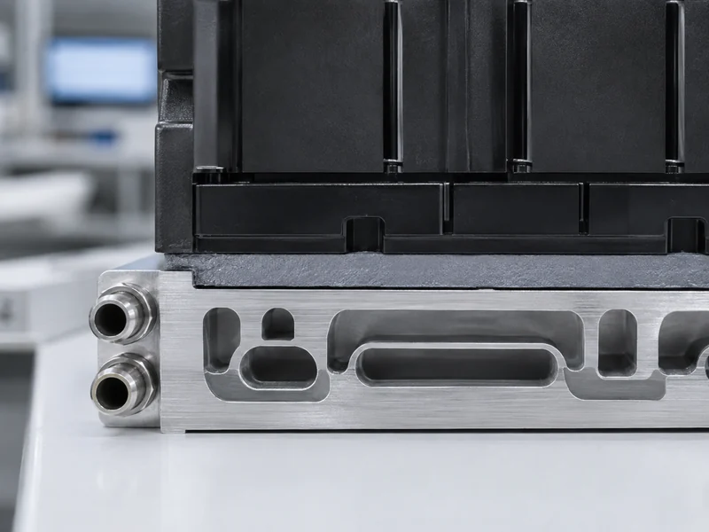
The thermal interface is usually where design and test meet most visibly. Gap, flatness, assembly stress, and how completely the material fills the bondline determine the real thermal path. That is why the choice and application of a thermal interface material for battery modules can move a module’s measured temperature rise more than a change in coolant flow. Teams that treat cooling components, interface materials, and structural bonding as one matched system tend to see fewer surprises when the module reaches thermal validation. Where a cooling design needs to be adjusted after test, it is worth confirming whether the issue is the plate, the interface material, or the contact pressure before changing all three at once.
What Module-Level Testing Really Tells You
The core takeaway is that a module test measures the assembly, not just the cells inside it, and that distinction is the one most often lost. Good cell data is necessary but not sufficient: the interconnects, welds, contact pressure, and thermal path introduced during assembly can shift resistance, temperature spread, and safety behavior enough to change a design decision. When a module underperforms, the productive first questions are usually about the joints and the thermal interface, not the cells.
Read a test scope by checking that it covers all four categories—electrical, thermal, mechanical, environmental—and that the safety tests reflect the right application standard. Plan the thermal tests together with the cooling and interface-material design, so a poor result points to one specific variable and not a general shortfall. For teams integrating cells, interface materials, structural bonding, and liquid cooling, the value of module testing is that it confirms the matched system behaves as designed before the pack is built around it.
FAQ
What is the difference between cell, module, and pack testing?
Cell, module, and pack testing answer three different questions in sequence. Cell testing characterizes the electrochemistry of an individual cell; module testing verifies that a group of interconnected cells still performs after assembly, including the effects of busbars, welds, and thermal contact; pack testing adds the enclosure, full BMS, and system-level safety and thermal behavior. Each level catches problems the previous one cannot see.
Which standards apply to EV battery module testing?
Several standards typically apply, depending on the application and market. For electric vehicles, teams commonly reference IEC 62660 for cell performance, UL 2580 at the system level, and SAE J2464 for abuse testing, with UN 38.3 required for transport. Fire and propagation work often follows UL 9540A. The exact set and current editions should be confirmed against the published standards for the target market.
How is thermal runaway tested at the module level?
Thermal runaway is tested at the module level by triggering a single cell into failure and observing whether heat propagates to adjacent cells. Trigger methods include heating, overcharge, short circuit, and mechanical penetration. Because propagation depends on cell spacing, interconnects, and the cooling path, this behavior can only be assessed on an assembled module, not on a single cell.
Why do busbar resistance and weld quality matter in module testing?
Busbar resistance and weld quality matter because they add series resistance and create uneven current paths that raise a module’s effective internal resistance and cause localized heating. A marginal weld can pass at low current and then fail under load, so connection integrity and resistance mapping are core module-level checks even when every cell has already passed its own screening.
What test parameters change once cells are assembled into a module?
Assembly introduces parameters that no cell test measures: interconnect and busbar resistance, weld and joint integrity, contact pressure against cooling surfaces, and temperature uniformity across cells. These variables can shift measured resistance, heat generation, and safety behavior, which is why module data has to be gathered on the assembled module and cannot be inferred from cell results.
Further Reading
- Battery Test Methods and Specifications — Industry technical resource summarizing how major UL, IEC, SAE, and UN standards map to specific battery test methods; supports this article’s standards overview.
- Cell, Module, and Pack Battery Testing Solutions for EVs — Industry vendor technical resource covering cell, module, and pack battery testing for EVs, including electrical and thermal/abuse methods; supports this article’s test-hierarchy and categories overview.
Related Articles
- Vapor Chamber Cooling — Explains how vapor chambers spread heat in EV batteries and electronics, useful when a module’s thermal path needs more than a cold plate.
- Why Battery Protection Matters Electric Vehicle — Covers how cell, module, and BMS protection work together, background for the safety behavior module testing verifies.
- What Is TEC Cooling? — Introduces thermoelectric (Peltier) cooling for precise, reversible temperature control when passive cooling cannot hold a target.
- How to Choose a Battery Energy Storage System Configuration — Walks through the subsystems and power-to-energy trade-offs behind an ESS design that module testing ultimately feeds.
- Install Liquid Cold Plates Step by Step — A practical guide to mounting cold plates for stable contact and repeatable temperatures, the same interface variables that drive module thermal results.
