
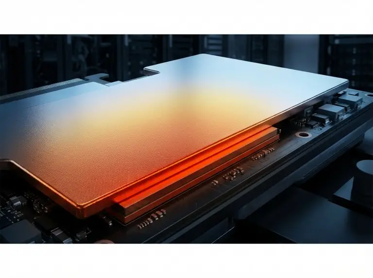
Vapor chamber cooling performance depends on evaporator geometry, wick capillary pressure, working fluid latent heat, and condenser-side heat transfer. Effective thermal conductivity equivalents of 10,000–20,000 W/m·K are achievable. The exact value depends on chamber geometry and power level. Thin-profile consumer electronics chambers sit at the low end. In contrast, large-format, high-power configurations reach the upper range. These parameters interact in ways that make vapor chamber selection different from choosing solid conductors or single-phase liquid cooling.
At Trumonytechs, we apply vapor chamber design across EV battery modules, 5G base stations, AI accelerator boards, and consumer electronics. Specifically, we use them where heat flux exceeds what conduction-only solutions can manage.
Scope note: This article covers vapor chamber thermal management for commercial electronics, EV battery systems, 5G infrastructure, and industrial power electronics. It does not cover spacecraft heat rejection, nuclear thermal management, or structures under sustained radiation exposure and extreme pressure cycling.
How Vapor Chamber Cooling Works?
Vapor chamber cooling depends on three variables: evaporator heat flux density, vapor core pressure equilibrium, and wick capillary pumping rate. All three interact to set the maximum heat transport rate before dry-out begins. Unlike solid copper, vapor chambers use the latent heat of vaporization — approximately 2,260 kJ/kg for deionized water at standard pressure — to move thermal energy across the full chamber area at once. We verify that each application’s temperature range and heat source geometry match the correct evaporator zone sizing before we finalize any layout.
The Evaporation-Condensation Cycle
At the heat source contact zone, working fluid in the wick absorbs enough energy to vaporize. The vapor then expands laterally across the vapor core toward cooler regions. There, it condenses on the inner surfaces and releases stored latent heat. As a result, condensed liquid returns to the evaporator by capillary pressure within the wick. This is a continuous, passive cycle. No pump or moving components are required.
This phase change cycle runs at near-isothermal conditions. For example, temperature variation across the condenser surface can be held to 1–3°C under steady-state loading. That distinguishes vapor chambers from bulk conductivity spreaders, where temperature gradients scale linearly with distance from the heat source.
Why 2D Spreading Matters
When a 1 cm² evaporator contacts a heat source and the condenser spans 100 cm², spreading resistance collapses. Therefore, vapor chambers achieve junction-to-ambient thermal resistance improvements of 30–50% over equivalent copper spreaders at power densities above 50 W/cm².

Vapor Chamber vs. Heat Pipes vs. Liquid Cooling
Heat pipe versus vapor chamber selection depends on heat source geometry, spreading area, orientation constraint, and power density. Heat pipe cooling is simpler and cheaper below approximately 50 W/cm² for point-source loads. However, vapor chambers become necessary above that threshold when 2D spreading is required. A vapor chamber is not a flattened heat pipe. The geometric difference produces entirely different thermal transport physics.
One-Dimensional vs. Two-Dimensional Transport
A heat pipe moves heat in one axial direction — from evaporator to condenser. In contrast, a vapor chamber moves heat radially in two dimensions from any evaporator point to the full condenser area. It creates an isothermal spreading plate, not a point-to-point link. For example, when a die-level heat source is 5–15 mm wide and the heat sink base is 50–100 mm wide, the vapor chamber’s 2D transport solves the spreading resistance that heat pipes cannot.
Liquid cooling becomes the better choice when sustained TDP exceeds approximately 200 W. At that point, passive cooling within the available condenser envelope is no longer practical. However, Vapor chambers deliver reliable, passive heat spreading with no pumps, tubing, or maintenance — for a broader view of passive vs active thermal management trade-offs, see our dedicated guide. This makes them the preferred choice for compact devices and moderate TDP loads. In high-density server and AI accelerator deployments, vapor chambers and liquid cold plates are often paired. Specifically, the vapor chamber handles die-level spreading and hotspot reduction, while the liquid loop manages bulk heat rejection at the rack level.
Orientation Sensitivity
Orientation sensitivity is a key decision factor. In our field deployments, sintered wicks hold greater than 90% of horizontal-position Qmax in vertical and inverted orientations — typically 5–10% Qmax loss. In contrast, grooved wick designs lose 30–50% Qmax when gravity opposes condensate return. As a result, we specify wick architecture based on actual installation orientation, not bench-test performance alone.
| Parameter | Vapor Chamber | Heat Pipe | Solid Copper Spreader |
|---|---|---|---|
| Effective thermal conductivity | 10,000–20,000 W/m·K equivalent | 50,000–100,000 W/m·K axial | 385–398 W/m·K |
| Heat transport geometry | 2D planar spreading | 1D axial transport | 3D conduction |
| Power handling (typical) | Up to 450 W per device | 5–150 W per pipe | Limited by spreading resistance |
| Orientation sensitivity | Sintered: 5–10% Qmax loss; Grooved: 30–50% loss vertical/inverted | Moderate to high | None |
| Form factor | Flat plate, 0.4–6 mm thick | Cylindrical, 3–12 mm diameter | Custom machined plate |
| Weight | Light (hollow chamber) | Very light | Heavy |
| Cost | Higher than heat pipe, lower than active cooling | Lowest passive option | Low to moderate |
| Best application | High power density, 2D spreading required | Point-to-remote heat transfer, cost-sensitive | Low power, high mechanical robustness |
Housing Materials and Wick Architecture
Housing material sets the upper boundary of thermal performance. Additionally, wick architecture determines whether that performance holds under orientation change, high heat flux, or extended thermal cycling. We confirm fluid compatibility across all three primary housing materials before we finalize any specification.
Note: Thermal conductivity values cited at 20°C. Values vary ±5–10% across the 30–150°C electronics operating range. Manufacturer datasheets are required for design-critical applications.
Copper offers the highest thermal conductivity and works well with deionized water. Therefore, it is the default for CPUs, GPUs, and high-power modules. Aluminum cuts weight by approximately 70% compared to copper. However, it needs compatibility management — water reacts with aluminum, so ammonia or surface treatment is required. Titanium serves aerospace and biomedical applications where corrosion resistance and fatigue strength under extreme thermal cycling matter more than cost.
Sintered metal wicks generate capillary pressure high enough to sustain condensate return in all orientations. As a result, they are the preferred choice where dry-out resistance and orientation independence are critical. Sintered copper powder is compressed to 40–70% void fraction. This gives both high capillary pressure and sufficient permeability for condensate flow. In our EV battery module projects, for example, charge ratio variation is the most common cause of critical heat flux exceedance at first power-on. That finding drove our adoption of gravimetric fill verification and hermetic leak-rate testing before customer handoff. We treat wick porosity as an active design variable and adjust it alongside vapor core thickness and evaporator zone area to hit application-specific Qmax targets.
Grooved wick structures give lower capillary pressure than sintered variants but higher vapor flow conductance in the horizontal position. Therefore, they work best when orientation is always horizontal and the main goal is moving high vapor volumes from a large, uniform heat source. Mesh wicks offer intermediate capillary pressure and suit applications where large-area manufacturing consistency is the priority.

Working Fluid Selection
Working fluid selection depends on operating temperature range, housing material compatibility, orientation requirements, and dielectric or toxicity constraints. Specifically, deionized water covers most electronics applications between 30°C and 150°C. However, methanol, ammonia, and fluorinated fluids handle conditions outside that range.
| Fluid | Operating Range | Compatible Housing | Latent Heat | Key Constraint |
|---|---|---|---|---|
| Deionized water | 30–150°C | Copper, stainless steel | ~2,260 kJ/kg | High purity required |
| Methanol | −40 to +120°C | Copper, aluminum | ~1,100 kJ/kg | Flammable, VOC regulations |
| Ammonia | −60 to +100°C | Aluminum, stainless | ~1,370 kJ/kg | Toxic, pressure vessel regulations |
| Fluorinated liquids | −60 to +150°C | Aluminum, copper | 80–160 kJ/kg | Low latent heat trade-off |
Deionized water carries the highest latent heat of any common working fluid — approximately 2,260 kJ/kg. However, high purity is required. Resistivity must typically exceed 10 MΩ·cm to prevent ionic contamination that corrodes copper and generates non-condensable gases. Therefore, We specify deionized water for all standard EV battery and electronics applications within the 30–150°C envelope. For single-phase loop applications, see our guide on working fluid selection for cold plate loops.
Methanol extends the lower boundary to −40°C for cold-climate infrastructure. Ammonia reaches approximately −78°C, but it requires pressure vessel handling. Fluorinated fluids are electrically non-conductive. As a result, they suit applications where a fluid leak cannot risk shorting active circuitry. However, their lower latent heat requires larger charge volumes and more condenser area to match water’s heat transport capacity.
Vapor Chamber Applications by Deployment Environment
Different variables drive vapor chamber specification in each domain. Consumer electronics demands flux concentration control. Infrastructure requires sustained TDP management. Additionally, automotive applications need voltage isolation and cycling durability. A chamber optimized for a smartphone will fail the sustained-load requirements of a 5G infrastructure module within hours of full activation.
Consumer Electronics — Smartphones and Gaming Laptops
Smartphone vapor chambers run below 0.4–0.6 mm thickness. Evaporator zones match SoC die footprints of 80–150 mm². The binding constraint is total thermal resistance to ambient through the device chassis — not peak heat flux. Therefore, we design for steady-state junction temperature limits. Smartphone thermal throttling is triggered by sustained temperature, not instantaneous power.
Ultra-thin vapor chambers — below 0.5 mm — are the dominant form factor in current flagship smartphones and compact wearables. At this thickness, vapor core height limits Qmax. These designs work because SoC heat flux is moderate and spreading distance is short, typically 50–80 mm. However, applications needing high Qmax over longer distances cannot sustain rated performance below 0.6 mm. As a result, we verify vapor core height against the Qmax calculation before we approve any ultra-thin design for production.
Gaming laptops must handle TDP values reaching 65–175 W in recent high-performance processor generations. Additionally, the chassis limits chamber thickness to 3–5 mm and hinge bend radius to 50 mm or greater. We size the evaporator zone to match the die footprint exactly — typically 35 × 45 mm for high-performance mobile CPUs. Oversized evaporator zones add thermal resistance between the die and the highest-capillary-pressure region of the wick.
5G Base Stations and AI Accelerators — Sustained TDP, Outdoor Conditions
Modules operating at 200–400 W in sealed outdoor enclosures with no forced airflow need vapor chambers that move heat to an external fin array across a 150–300 mm span. Therefore, our solutions for these platforms use sintered wick chambers rated for orientation independence. We validate charge ratios through 1,000-hour accelerated life testing at −40°C to +65°C ambient. We also design condenser surfaces for natural convection in zero-wind conditions.
In high-density AI server deployments — where data center liquid cooling architectures increasingly combine multiple thermal technologies — 3D vapor chambers are used alongside or instead of standard flat-plate designs.Specifically, a 3D vapor chamber extends the vapor space into vertical fin structures on the chamber body. This increases total condenser surface area within the same footprint. The design suits OCP accelerator modules and GPU cooling stacks where rack height is constrained but heat rejection area must be maximized. Wick selection, charge ratio control, and condenser area verification all apply the same way. However, the 3D geometry adds surface area without changing the capillary limit or dry-out failure modes.
EV Battery Thermal Management — Isolation, Cycling Durability, Cell Uniformity
EV battery thermal management imposes constraints absent from standard electronics cooling — and vapor chamber specification in this domain reflects that directly. These include electrical isolation between the working fluid and battery cells, resistance to 3,000–10,000 thermal cycles over vehicle lifetime, and cell-level temperature uniformity within ±2°C across a 200–400 mm module. We evaluate fluorinated fluids only when isolation cannot be achieved with sealed housing geometry alone. Additionally, titanium housings serve this application class when corrosion resistance and fatigue requirements under automotive vibration exceed what copper-water designs can sustain economically.
When Not to Specify a Vapor Chamber
Vapor chamber implementation fails most often from system-level mismatches. The three most common are inadequate condenser area for the sustained TDP, insufficient flatness at the evaporator contact surface, and use of a vapor chamber where a heat pipe plus copper spreader delivers equivalent performance at lower cost.
We find that vapor chamber specification below 30–40 W/cm² — combined with a source footprint larger than 25 × 25 mm — typically underperforms a copper spreading plate plus heat pipes. At this power density, for example, TIM resistance can contribute 25–35% of total junction-to-ambient resistance. As a result, vapor chamber gains seen in simulation disappear in physical validation.
Bending to radii below approximately 50 mm has been linked to greater than 15% performance degradation in copper housing designs. Additionally, evaporator surface flatness must be held within 50 µm. Beyond that, bond line variation dominates thermal resistance. Long-term performance also degrades through non-condensable gas buildup — mainly from uncontrolled brazing atmosphere. Therefore, our argon atmosphere brazing and in-situ charge validation remove the primary gas generation pathways before we seal the unit.
Conclusion
At Trumonytechs, verification starts with thermal stack decomposition. We isolate evaporator contact resistance, wick resistance, vapor core resistance, and condenser resistance as separate budget lines before we commit any geometry to tooling. The limiting term is rarely the vapor chamber itself. Instead, it is almost always the condenser area — allocated under the assumption that any vapor chamber will perform once the heat source is covered.
The failure we intercept most often is insufficient condenser area for the sustained TDP. Projects that size condenser area only for peak transient loading need a redesign cycle when we model steady-state condenser resistance under worst-case ambient and airflow conditions. As a result, finding this mismatch at thermal stack decomposition removes weeks of fabrication lead time.
When evaporator zone, wick architecture, charge ratio, and condenser area are each treated as independent design variables, the vapor chamber holds rated performance across the 30–150°C operating range. It also holds across the orientation, vibration, and thermal cycling conditions of deployment. Share your thermal boundary conditions with our team. We will analyze your heat flux density, condenser envelope, and TIM stack, and respond with a technology recommendation within 48 hours.
FAQ
What is the minimum power density that justifies a vapor chamber over a copper heat spreader?
Vapor chambers become justified when evaporator heat flux exceeds approximately 30–50 W/cm² and the condenser area is more than 4× the evaporator area. Below this threshold, solid copper with a heat pipe achieves equivalent performance at lower cost. Therefore, the crossover depends on heat source footprint and spreading distance, not power alone.
Can vapor chambers operate in any orientation?
Sintered wick vapor chambers work in all orientations. However, expect 5–10% Qmax reduction from horizontal baseline in worst-case orientation. Grooved wick designs need gravity-assisted condensate return. As a result, do not specify them for applications beyond ±30° from horizontal without verifying orientation-specific Qmax values with the manufacturer.
How thin can a vapor chamber be without significant performance loss?
Performance limits emerge below 0.4–0.6 mm total thickness. At that point, vapor core height cannot sustain the vapor velocity needed for full Qmax. Ultra-thin designs below 0.5 mm work in smartphones where spreading distance is short and heat flux is moderate. However, applications needing high Qmax over longer distances cannot sustain rated performance at this thickness.
When should a vapor chamber not be specified?
Avoid vapor chambers when evaporator heat flux falls below 30 W/cm², when the heat source footprint exceeds 25 × 25 mm with manageable spreading resistance in copper, or when the main thermal challenge is transport distance rather than local flux concentration. In these cases, a copper spreader plus heat pipe routing to a remote fin array delivers equivalent performance at lower cost.
What is the difference between a standard vapor chamber and a 3D vapor chamber?
A standard vapor chamber spreads heat in two dimensions across a flat plate. In contrast, a 3D vapor chamber extends the vapor space into vertical fin or tube structures on the chamber body. This increases total condenser surface area without expanding the base footprint. Therefore, 3D designs suit high-density server and AI accelerator applications where rack height is constrained but heat rejection area must be maximized. The same capillary limit, charge ratio, and dry-out failure modes apply to both.
