
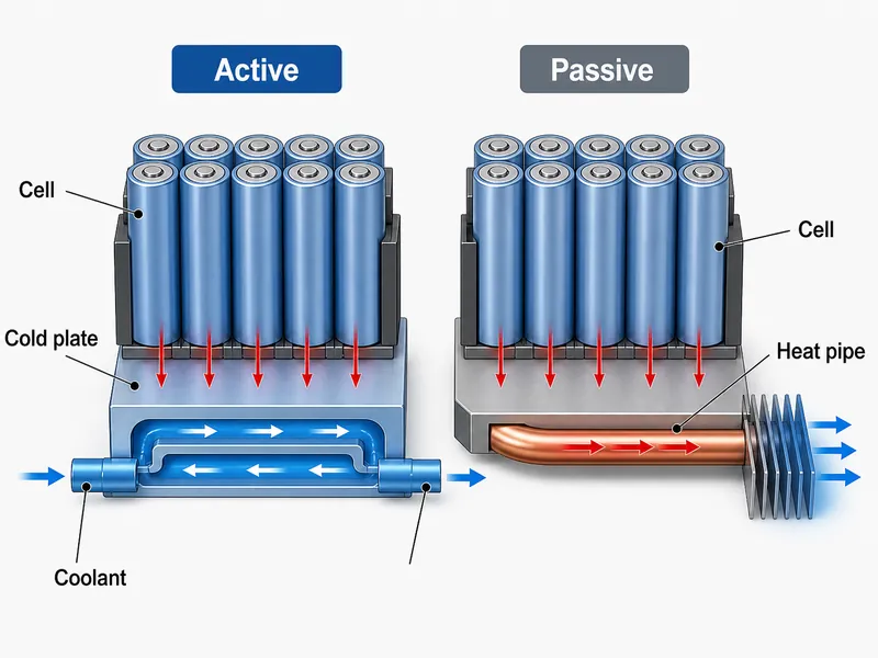
Active vs passive thermal management turns on one question for a battery pack: does the cooling path need external energy to move heat. Active methods spend pump, fan, or compressor power to force heat away from the cells. Passive methods rely only on conduction, natural convection, and phase change through fixed hardware. That distinction sets how much heat you can reject, how tight you can hold cell-to-cell temperature, and how much parasitic power and cost you carry for the life of the system. This article compares the two from the thermal management of battery packs perspective, not consumer electronics, and names the variables that decide which one fits a given pack.
The thermal problem in a battery pack
Holding the hottest cell inside a narrow band is the whole job of a pack’s thermal path. Peer-reviewed reviews report that lithium-ion cells are generally kept within roughly 20–40 °C, with performance and aging worsening once cells run much above ~40 °C, though the exact window shifts with cell chemistry and duty. A thermal path also has to keep the spread between cells small, because uneven temperature drives uneven aging across the pack.
Both goals push against the same physics. Heat generation rises with C-rate and fast charging, ambient conditions change the sink the pack rejects into, and the path between cell and coolant has a finite thermal resistance. Whether a passive path can meet those goals, or whether the pack needs a driven loop, follows from those numbers, not from preference.
What separates active from passive thermal management
One test separates the two approaches: whether the heat path needs external energy to move heat. Air, liquid, a solid conductor, or a two-phase device can each sit on either side of that line, depending on whether something drives the flow.
Active methods for a battery pack
Adding a driven flow lets active cooling reject heat regardless of ambient conditions. The common options for a pack, in rough order of heat-rejection capability:
- Forced-air cooling: a fan or blower pushes air across cells or a finned structure. It is simple and low cost, but the low heat capacity of air limits it and makes uniformity hard across a large module.
- Liquid cooling through a cold plate: coolant carries heat out of internal channels. For a comparable footprint it tends to move more heat and hold a tighter spread than air, though the gain depends on channel layout and contact resistance.
- Refrigerant or chiller-based cooling: couples the pack to a vapor-compression loop when ambient is too high for a liquid loop alone, at the cost of added complexity.
- Thermoelectric (TEC) modules: drive heat electrically for small, precise loads; low efficiency keeps them off most pack-scale designs.
The trade repeats in every case. You gain control and capacity, and you pay in pump or fan power, added components, and more failure points to maintain.
Passive methods for a battery pack
Moving heat with no driven flow makes passive cooling silent, free of parasitic power, and free of moving parts that can fail. The mechanisms a pack designer actually uses:
- Conductive spreading through the housing plus a thermal interface material — a thermal grease, gap filler, or structural thermal adhesive — to carry heat from cells into the surrounding structure.
- A heat pipe or vapor chamber, whose heat pipe cooling action uses evaporation and condensation of a working fluid to move heat quickly to a cooler region and spread hot spots inside an otherwise passive design.
- Phase change material (PCM), which absorbs heat as it melts and buffers short thermal peaks without any input power.
A passive path has a ceiling, and it is set by physics, not by a fixed wattage. The load such a path can carry is roughly the allowable cell-to-ambient temperature difference divided by the total thermal resistance of the path (Q ≤ ΔT / Rθ). When the load climbs past that, or when a hot ambient shrinks ΔT, the passive path runs out of headroom.
When passive cooling is enough — and when it isn’t
Passive cooling holds up only while heat generation is low, duty is intermittent, and the surroundings stay cool; break any one of those and its margin disappears. The call is not a preference, so it helps to run it as an ordered check instead of a single rule of thumb.
Work the decision in this order, and note that cell format and pack geometry change every input below:
- Heat generation and its duration. A short peak followed by long idle behaves differently from continuous high-C discharge; a passive path can ride out transients that would swamp it if sustained.
- Ambient and sink temperature. A hot climate erodes the temperature difference passive cooling depends on, so a design that works in a mild environment can fail in a hot one.
- Total thermal resistance and allowable temperature rise. Check the heat balance (Q ≤ ΔT / Rθ) at the worst-case load; if the hottest cell would drift toward the ~40 °C aging region, the passive path is out.
- Cell-to-cell uniformity target. When the binding constraint is a tight spread across the module rather than peak temperature alone, a driven loop usually earns its place.
- Active-loop flow, pressure drop, and failure modes. Once a driven loop is on the table, its pumping power and its pump, fan, and seal failure points enter the trade.
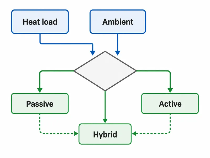
Reach for a passive design first when the pack dissipates modestly, discharge is gentle, and temperature swings are slow. A conductive path plus PCM buffering can hold cells in band with no input power, which protects range and removes pump and fan maintenance. That case is common in small or low-C-rate packs. Move toward active cooling as fast charging, high continuous discharge, or hot ambient enters the spec, because those are the conditions the heat balance above stops tolerating. Matching the method to heat load and cell-to-cell uniformity is the core of EV battery cooling design.
Active vs passive trade-offs for a battery pack
Read the trade-off by your binding constraint, not by which method sounds stronger. No approach is universally better; each trades heat capacity against parasitic power, cost, and reliability for a specific duty. The table below compares the two pure approaches and the hybrid middle ground on the variables that drive a pack decision.
| Decision variable | Passive | Active | Hybrid (active + passive) |
|---|---|---|---|
| Heat-load fit | Best for low, steady loads | Scales with coolant flow; suits high loads | Active carries peaks, passive rides transients |
| Cell-to-cell uniformity | Harder to hold across a large module | Channel-based cooling can hold a tighter spread | PCM or spreader smooths transients |
| Parasitic power | None | Pump, fan, or compressor draw | Lower average than continuous active |
| Cost and complexity | Lowest | Highest; more components | Between the two |
| Reliability / failure mode | No moving parts | Pump, fan, seal, and leak points to maintain | Fewer active-duty hours |
| High transient / fast charge | Limited headroom | Handles high transient heat | Handles peaks with buffering |
The table’s ratings are directional, not fixed grades. Cell format, pack geometry, total thermal resistance, contact interface, and flow and pressure-drop targets can move any row, so verify a specific pack against a thermal model before locking the architecture. As a decision, though, the pattern holds: protect range on a modest load and passive wins; refuse to let peak heat or a hot-climate duty cycle violate the cell limit and active wins despite its cost; face a spiky load and a hybrid path often reads best.
Hybrid thermal management
Reach for a hybrid path when the duty cycle is spiky, with long quiet stretches punctuated by short high-power events, so no single method has to cover both. In practice a driven liquid loop or forced-air loop handles steady and peak heat, while PCM, heat pipes, or a conductive spreader flatten short spikes and even out temperature between the driven cooling events.
The payoff is duty-cycle efficiency. A passive layer absorbs transients that would otherwise force the active system to oversize or run continuously, which cuts average parasitic power and lowers the active-duty hours on pumps and fans. One study included in a battery thermal management review reported a hybrid liquid/heat-pipe design holding maximum cell temperature near 34 °C, with about a 1 °C spread under its specific discharge condition. That result is tied to that cell format, rate, and coupling, so it does not generalize. Hybrid earns its added integration effort when a single approach forces a bad compromise: a passive design that cannot hold peaks, or an active design that runs oversized for rare events.
How simulation validates the chosen thermal path
Simulation answers three questions hardware cannot show until it exists: the pressure drop, the cell temperature spread, and whether coolant reaches every part of the module. At Trumonytechs we run 3D CFD (STAR-CCM+) for component-level behavior inside the pack and 1D system simulation (Amesim) for the whole thermal loop. The analysis targets the values that decide whether a design holds cells in band: pressure drop, the temperature difference between cold-plate inlet and outlet, the temperature difference across the cold-plate surface, and the maximum and minimum cell temperatures.
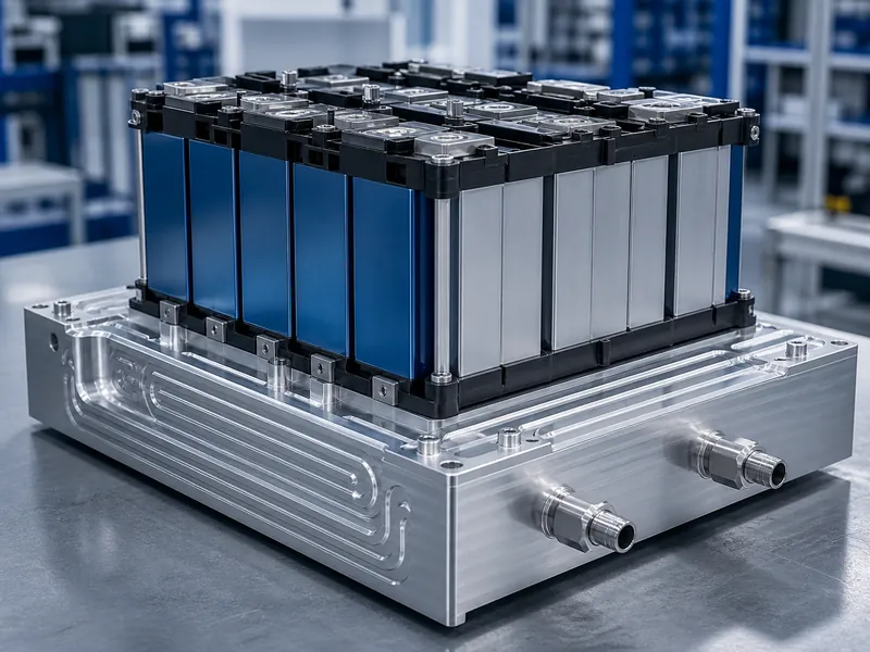
Each output maps to a decision. Predicted temperature distribution shows whether the hottest cell stays inside the operating band. Predicted flow and pressure distribution show whether a liquid path cools evenly or starves part of the module. Pressure drop shows the parasitic pumping cost the design commits to. Running this before committing tooling separates a cold-plate or liquid cooling system design that meets its uniformity target from one that looks fine on a drawing but fails on the bench.
Conclusion
The deciding variables are heat load, ambient temperature, and the cell-to-cell uniformity the pack must hold, not a preference for the cheaper or the more capable option. Passive cooling is the right choice where the heat balance closes on a modest, intermittent load in a cool environment, since zero parasitic power and no moving parts are a real advantage there. A driven loop, and often a liquid cold plate, becomes the better call once fast charging, sustained high discharge, hot ambient, or a tight uniformity target enters the spec and the passive margin runs out. A hybrid design fits the spiky loads in between. The common mistake is settling this on cost alone; instead, check the worst-case load and ambient against a simulated pressure-drop and temperature-spread result before the architecture is fixed.
FAQ
Do I need active cooling for an EV battery pack, or is passive enough?
Passive is worth trying first only when the pack’s heat generation is low and its surroundings stay cool. The deciding test is whether a passive path’s thermal resistance can still hold the hottest cell below roughly 40 °C at your worst-case load and ambient. Fast charging or high continuous discharge usually pushes past that point, and a driven loop then earns its cost.
What heat load makes passive cooling insufficient for a battery module?
There is no single wattage. The limit is where the load exceeds the allowable cell-to-ambient temperature difference divided by the path’s thermal resistance. Passive air paths are often cited in the low hundreds of watts, but that figure depends on surface area, allowable rise, and ambient, so treat it as an order-of-magnitude starting point and confirm it with a heat balance for your pack.
Which approach keeps cell-to-cell temperature difference lower?
Channel-based liquid cooling tends to hold a tighter cell-to-cell spread than air or purely passive designs across a large module, because coolant removes heat more evenly. The margin still depends on channel layout and contact resistance. Where the problem is transients instead of steady load, adding a PCM layer helps more than raising active capacity.
When should I switch from a heat-sink or PCM design to a liquid cold plate?
Switch when peak heat during fast charge or a hot climate pushes the hottest cell toward the aging region, or when cell-to-cell uniformity becomes the binding constraint. A spreader-based heat sink reaches its limit before a channel-based cold plate does, because a fixed conductor cannot raise its heat removal once the load climbs.
Further Reading
- Advances and Challenges in the Battery Thermal Management Systems of Electric Vehicles — peer-reviewed review (Materials, 2025). Supports the passive / active / hybrid classification and the case for hybrid designs under demanding duty cycles.
- Parameter effect quantification for a phase change material-based lithium-ion battery thermal management system — peer-reviewed study (Turkish Journal of Chemistry, 2022). Supports the ~20–40 °C operating window and the role of PCM in buffering thermal peaks.
Related Articles
- Thermal Management: The Importance and Benefits of Optimum Performance — why holding components in their temperature band protects performance and service life.
- Why Is Thermal Management Important? — the baseline case for managing heat before you pick a cooling method.
- Install Liquid Cold Plates Step by Step — how a liquid cold plate is mounted to a module once you commit to active cooling.
- Why Do Golf Carts Choose Liquid Cooling Over Air Cooling? — a worked active-versus-passive trade-off in a real vehicle class.
- Best Materials for Dissipating Heat in Electronics — the conductive materials and interfaces a passive path depends on.
