
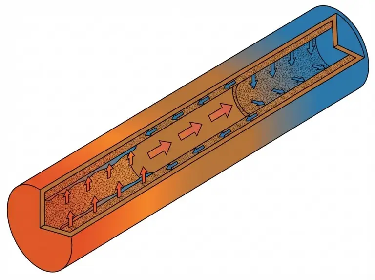
A heat pipe moves heat from a focused source to a remote rejection surface. It does this passively, with no pump, no fan, and no external power. But whether a heat pipe fits your design depends on four factors. These are working fluid temperature range, installation orientation, wick capillary pressure, and downstream rejection quality.
We at Trumonytechs assess heat pipe suitability as part of a broader thermal management portfolio. That portfolio includes liquid cold plates and thermal interface materials. Our selection process matches the transport mechanism to the actual power density, orientation envelope, and lifecycle requirements of each project.
What Heat Pipes Are and How They Work
A heat pipe is a sealed, evacuated metallic vessel. Copper is the most common envelope material for electronics cooling. Aluminum, titanium, and stainless steel also serve as envelope materials, depending on the working fluid and operating temperature. Inside the vessel sits a small charge of working fluid and a capillary wick structure.
When heat enters the evaporator end, the fluid vaporizes. Vapor travels to the cooler condenser end and releases latent heat. The liquid then returns to the evaporator through the wick by capillary force. No moving parts sustain this cycle.
This sets heat pipes apart from thermosyphons. Thermosyphons rely on gravity alone to return condensate. They require the condenser to sit above the evaporator. Heat pipes with capillary wicks can operate in orientations that thermosyphons cannot.
The envelope is also a sealed pressure vessel. Internal pressure varies with the working fluid’s saturation temperature. The vessel must resist internal vapor pressure at peak temperature and external atmospheric pressure at cold startup.
A heat pipe’s effective thermal conductivity can be orders of magnitude higher than solid copper. But the usable value depends on pipe length, diameter, wick structure, and power load. Published ranges vary widely. Treat them as reference points, not fixed material properties. Transport capacity is a system-level output, not a catalog number.
Why Thermal Engineers Choose Heat Pipes
Heat pipes solve a specific problem. They move heat passively over a distance that solid conduction cannot cover within the temperature budget. Four core advantages drive selection:
- No moving parts, zero power draw:The phase-change cycle sustains itself as long as a temperature gap exists between evaporator and condenser. No fan or pump to fail. This matters most in battery-powered devices, sealed enclosures, and remote sites with no power budget for active cooling.
- High thermal conductivity in a compact form: A copper-water heat pipe moves heat at rates that would need a solid copper bar many times its cross-section. This matters most in tight layouts where routing a thick copper block from source to sink is not feasible.
- Long service life, minimal maintenance:Well-made heat pipes with compatible fluid-envelope pairings and verified degassing have shown lifetimes beyond 10–15 years under stable conditions. This is a reachable benchmark, not a blanket guarantee. It depends on material quality, process control, and operating environment. Best suited for sealed systems with no maintenance access: 5G base stations, embedded industrial controls, ESS enclosures.
- Vibration and shock tolerance:No moving parts and no liquid reservoir exposed to sloshing. Heat pipes handle vibration levels that would shorten the life of pumped liquid loops. Best suited for vehicle-mounted electronics, industrial equipment, and ruggedized systems.
We recommend heat pipes when these advantages outweigh the thermal resistance floor that active liquid cooling can reach. The design must be checked through prototype testing under real boundary conditions.
How Wick Structure and Working Fluid Determine Performance
Wick type and working fluid set the ceiling on what a heat pipe can do. The wick controls capillary return pressure, maximum heat flux, and orientation tolerance. The working fluid sets the operating temperature range and latent heat capacity.
Working Fluid Selection
Each fluid-envelope pairing must be verified for chemical compatibility through life testing. The compatibility issue is fluid-envelope specific, not envelope-universal. Aluminum reacts with water and generates hydrogen gas over time. That makes aluminum-water not compatible. But aluminum-ammonia is a proven, reliable combination.
- Copper-Water: Practical range ~20–150°C. Some designers treat 25°C as the realistic lower bound for full two-phase operation. This is the default for most ground-based electronics cooling.
- Aluminum-Ammonia: Practical range ~−70°C to 60°C. Common in spacecraft thermal control and cold-region industrial systems.
- Copper-Methanol: Extends below water’s practical floor, down to ~−40°C. Used in ground-based electronics that must operate below 20°C ambient.
We specify wick type and envelope material from a compatibility matrix. Life test data must verify the matrix before any design moves to prototyping.
Wick Type Selection
In projects where orientation is uncertain at the design stage, we default to sintered wicks. We absorb the cost premium rather than risk a wick redesign after prototype testing.
- Sintered Powder Wick: Highest capillary pressure. Works well against gravity and at adverse tilt angles. Higher cost. Best fit for variable orientation, high heat flux, and long-life designs.
- Axial Groove Wick: Lower capillary pressure. Loses performance beyond ~30–45° adverse tilt. Lower cost. Best fit for fixed gravity-assisted orientation and cost-sensitive builds.
- Mesh / Screen Wick: Medium capillary pressure. Moderate tolerance to tilt and horizontal use. Medium cost. Best fit for mid-range orientation and cost requirements.

Charge Volume Control
Charge volume must be precise:
- Overfilling raises flow resistance.
- Underfilling causes partial dry-out under peak loads.
- The most common issue we see during design review is an underspecified fill tolerance. This creates unit-to-unit thermal resistance spread in production volumes.
Types of Heat Pipes and When Each Geometry Fits
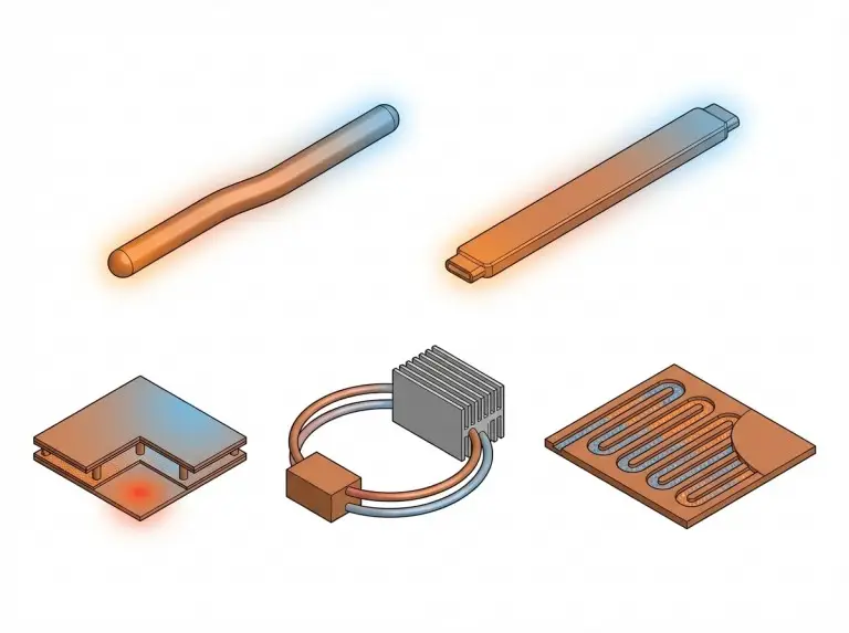
Geometry selection depends on power density, installation space, orientation, vibration, and cost. We map these variables to a decision matrix before committing to prototype tooling.
Standard Round Capillary Heat Pipes
Round capillary heat pipes in the 4–12 mm OD range are the default for point-to-remote-sink transport. They serve telecom hardware, industrial controls, and mid-power electronics. They bend around obstacles and are cost-effective at volume. Their limitation is small source contact area. A spreader plate is often needed when the source footprint exceeds the pipe diameter.
A single pipe’s transport capacity varies with length, temperature, orientation, bending, and wick design. Published data for a 6 mm sintered wick pipe show 30–65W per pipe at moderate lengths in gravity-assisted orientation. This number shifts with every design variable. Using 75% of rated Qmax as a safety margin is common practice. We size heat pipes against specific boundary conditions and confirm with prototype tests.
Flat Heat Pipes
Flat heat pipes offer a wider contact surface. They fit board-level space constraints where round mounting is impractical. The narrower vapor space creates asymmetric capillary behavior. Wick design must account for this.
Vapor Chambers
Vapor chambers spread heat from a small, high-flux source across a large planar area. They make sense when spreading resistance through a solid copper base would use too much of the temperature budget. Higher tooling cost and greater thickness limit them to specific use cases. We match vapor chamber recommendations to source footprint and power density rather than applying a fixed geometry rule.
Loop and Pulsating Heat Pipes
Loop heat pipes (LHPs) separate the evaporator from the condenser transport line. This allows longer transport distances and flexible routing. Pulsating heat pipes (PHPs) use oscillating slug flow instead of capillary return. They show strong potential for vibration-tolerant and adverse-orientation applications in power electronics and EV battery thermal management.
Heat Pipe Applications Across Industries
Heat pipes appear in nearly every sector that needs passive, maintenance-free heat transport. The right fit depends on source power density, installation space, orientation profile, and cost.
Consumer Electronics
In laptops, tablets, and smartphones, heat pipes are the dominant passive transport solution. They are thin, bendable, lightweight, and made at consumer-market volumes. A typical laptop routes flattened copper-water pipes from CPU and GPU die pads to a shared finned condenser. That condenser sits at the chassis exhaust. The limiting factor here is rarely the pipe itself. It is condenser airflow and fin density at the rejection end.
Data Centers and Telecom
Heat pipes extend CPU heat sink reach to chassis-level airflow paths in air-cooled servers. They do this without pumped liquid loops. As server power density climbs above 300–500W per socket, direct liquid cooling is replacing air-cooled heat pipe designs. This shift is happening at the rack level. But heat pipes remain cost-effective in mid-density servers and 5G base station housings where liquid infrastructure is not installed.
Our review of heat pipe fit in data center applications includes rack-level airflow mapping. A correctly sized heat pipe in a poorly managed airflow path fails the same way. An undersized pipe in a well-managed path produces the same result.
EV Battery and Energy Storage Systems
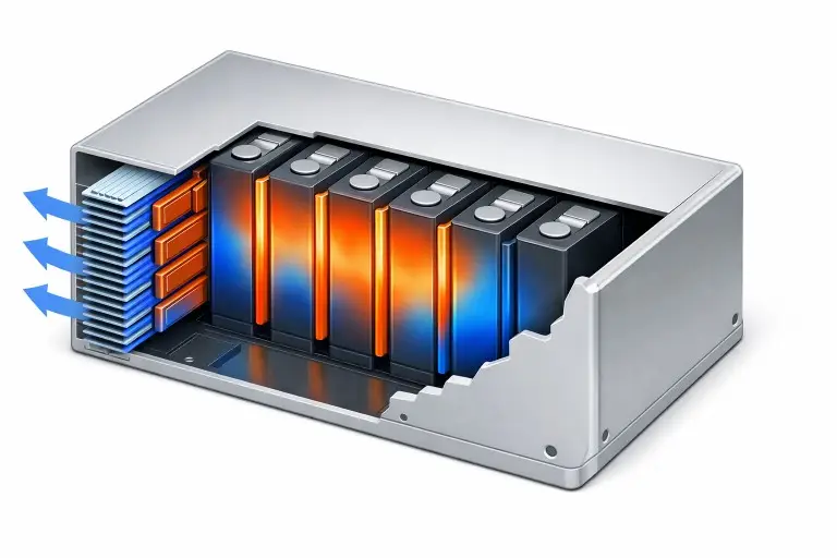
Battery and ESS applications present the most demanding heat pipe profile. Though EV and ESS batteries share similar cell chemistries, their thermal management needs differ. Both involve large module footprints, tight installation depth, strict cell-to-cell temperature uniformity, and orientation changes during operation.
In ESS integration projects our team has completed, heat pipe spreading between cells cut peak temperature variance to under 5°C. This target is a widely adopted design goal in battery thermal management for cell balance and cycle life. Passive heat pipe cooling works for moderate discharge rates where flux density stays within wick capacity and orientation is controlled. For high-rate fast-charging, active liquid cooling is often needed. Learn more about the full scope of EV battery cooling challenges and solutions.
Industrial Power Electronics
Power converters, motor drives, and inverters produce focused heat in enclosed cabinets with limited airflow. Heat pipes move that heat to cabinet-wall-mounted sinks or external fin stacks. They do this without breaking the sealed enclosure. This preserves IP-rated protection while keeping thermal performance on target. We assess heat pipe routing and condenser sizing alongside the enclosure’s ingress protection rating. The thermal path must not compromise the mechanical seal.
Operating Limits, Failure Modes, and When to Transition to Liquid Cooling
Every heat pipe has operating limits. These must be verified against the deployment profile before the design is locked. The most costly error is treating the heat pipe as a standalone cooler. A heat pipe transports heat. It does not reject it. The condenser end still needs a finned heat sink, a cold plate, or forced airflow. Size it for full power at worst-case ambient.
Orientation Limits
Standard axial groove wicks perform best when gravity assists liquid return. Horizontal operation is acceptable for sintered and mesh designs. Adverse orientation needs verified capillary pressure margin that exceeds the hydrostatic head at the worst-case tilt angle. Dynamic conditions matter too — vehicle cornering, equipment handling, and seismic loading all count.
In one EV battery integration review, our team found that the assumed horizontal orientation was inverted during vehicle cornering. The original thermal spec did not capture this. That required a full wick redesign. We now require orientation in the thermal boundary document before wick selection.
Power Density and Dry-Out
Each wick geometry has a maximum heat flux before evaporation outpaces capillary return. Exceeding it causes abrupt thermal resistance increase, not gradual degradation. We size the safety margin per project using vendor-specific test data. We do not apply a fixed percentage across all designs.
Ambient Temperature Effects
When high ambient conditions shrink the evaporator-to-condenser temperature gap, vapor flow weakens. Thermal resistance climbs. We see this most in outdoor equipment enclosures and high-ambient EV deployments. The fix is to verify the minimum usable temperature gap across the full operating range.
NCG Buildup
Non-condensable gas migrates to the condenser over time. It reduces active condenser area and raises thermal resistance. The best fix is strict control of envelope material purity, working fluid grade, and degassing procedure. This must be verified through life testing at the point of manufacture, not assumed from material certificates.
High-purity copper envelopes paired with degassed water are a proven approach. But fit must be checked against the target application’s cycling profile and required service life.
When Heat Pipes Are No Longer Enough
Heat pipes become the wrong choice in three situations. Power density exceeds the dry-out limit. Orientation constraints cannot be resolved by wick selection. Or the thermal resistance target drops below what passive two-phase transport can achieve. The crossover point is a design output, not a universal threshold. We evaluate both heat pipe and liquid cold plate options against project-specific conditions before recommending either.
Fit verification before committing: Confirm orientation margin, including dynamic loads. Verify power density headroom below wick dry-out threshold. Check condenser temperature gap under worst-case ambient. Confirm startup temperature above working fluid operating floor. Verify NCG control through life testing. Size the rejection surface for full load. Confirm envelope pressure integrity across the operating temperature range.
Conclusion
Heat pipe cooling delivers passive, maintenance-free heat transport far beyond solid copper. But it only works when wick type, working fluid, orientation envelope, and downstream rejection match the actual deployment conditions. Prototype testing must validate the design.
We bring liquid cold plate, thermal interface material, and system-level integration experience. Our work spans EV battery packs, ESS modules, and industrial power electronics. When heat pipe boundary conditions are tight, we verify orientation margin, power density headroom, and long-term NCG stability. The design does not leave our engineering team until those checks pass.
To find out if heat pipe cooling fits your project, contact us. Send your power dissipation map, orientation constraints, ambient temperature range, and target thermal resistance
FAQ
What is the maximum power a heat pipe can transfer?
No universal maximum exists. Capacity depends on diameter, length, wick type, fluid, temperature, and orientation. Size against your boundary conditions and confirm with tests.
Can heat pipes work upside down or in zero gravity?
Sintered powder and mesh wicks can. Axial groove designs cannot. Verify capillary pressure margin against the specific tilt angle and heat load.
How do heat pipes fail?
Two primary modes: dry-out (abrupt temperature spike) and NCG buildup (gradual resistance increase). Both are preventable through correct wick selection, fill procedure, and envelope specification.
What is the typical design life?
Well-made copper-water heat pipes with high-purity envelopes and verified degassed fill have shown over 10–15 years under stable conditions. Extreme cycling requires deployment-specific life testing.
How do I choose between a heat pipe and a liquid cold plate?
If power density, orientation, and thermal resistance targets all fall within verified passive two-phase limits, heat pipes cost less. They also need less maintenance. Beyond those limits, liquid cooling is more reliable. The crossover is project-specific.
