
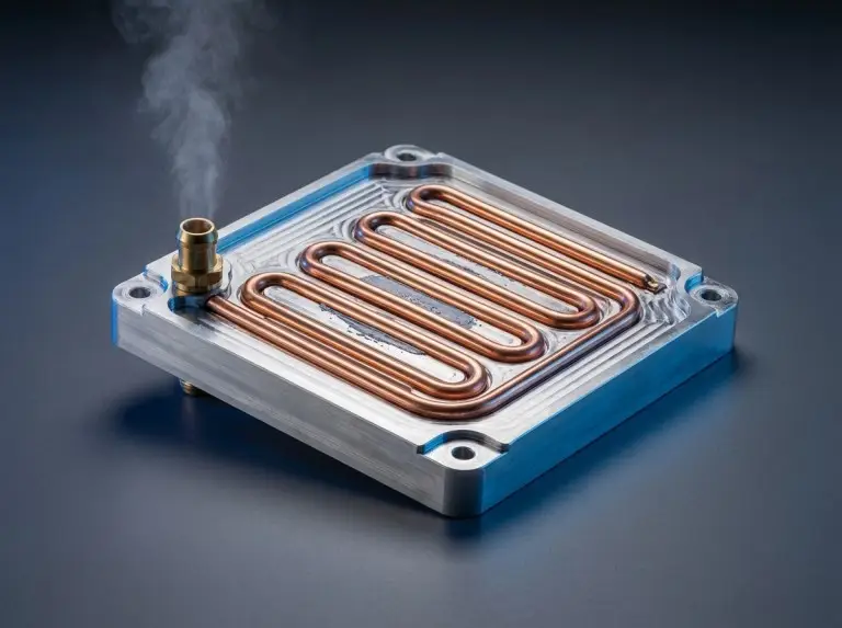
A tubed cold plate is a liquid cooling part. It has copper or stainless-steel tubing pressed or bonded into a channeled aluminum base plate. The tube creates a direct heat path between a hot device and the coolant. Tube material, attachment method, and flow path all shape how well it works — and whether tubed construction fits a given heat load, coolant type, and pressure range.
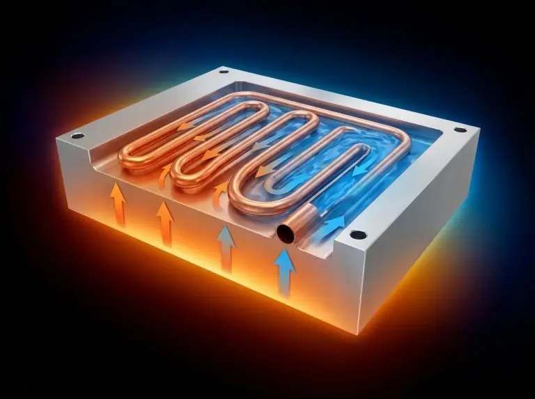
How a Tubed Cold Plate Transfers Heat?
A tubed cold plate removes heat in two steps. First, conduction moves heat from the mounted component through the plate and into the tube wall. Then, forced convection inside the tube moves that heat into the flowing coolant. The coolant — usually water, a glycol-water mix, or a dielectric fluid — flows to a remote heat exchanger, dumps the heat, and returns via pump.
The number of material interfaces between the component and the coolant sets the length of the thermal path. In exposed-tube and press-lock designs, the tube sits flush with or just below the plate surface. This keeps the interface count low. In buried-tube epoxy-fill designs, the epoxy adds one interface. Whether thermal resistance goes up or down depends on the epoxy’s conductivity and fill quality versus the air gaps it replaces.
A tubed cold plate is one part of a larger hydraulic loop. To understand how the full loop works together, see our guide onhow liquid cold plates work. Stable operating temperature needs the full system to work — pump head, heat rejection, coolant properties, reservoir, degas, and controls. We check this scope at the start of every project. A well-specified cold plate cannot fix an undersized pump or heat exchanger.
Exposed, Buried, and Press-Fit
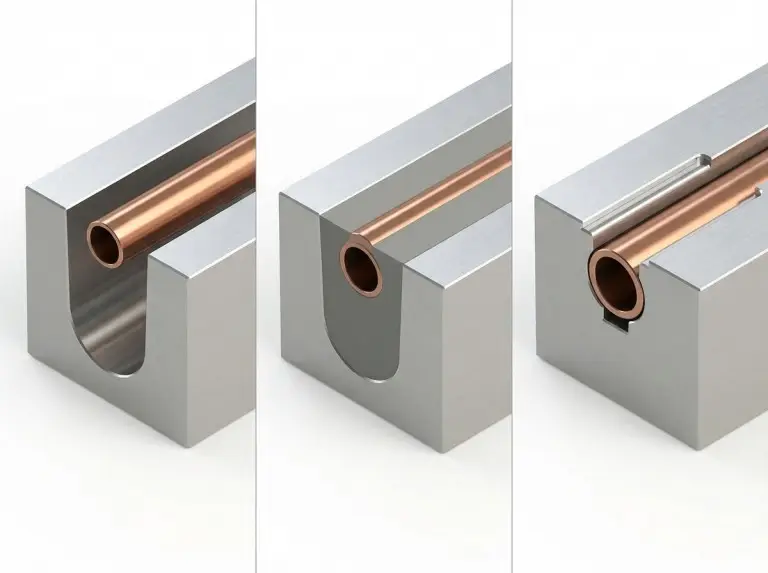
Tubed cold plates come in three types. Each one affects thermal performance, build complexity, and durability in different ways.
The exposed-tube design places the tube in machined channels. The tube stays visible on the plate surface. This is the simplest option. Contact quality between tube and channel must be checked along the full flow path during acceptance.
The buried-tube (epoxy-fill) type covers the pressed tube with thermally conductive epoxy. The epoxy fills voids and can improve contact uniformity — but only when the fill process is well controlled. Whether voids are truly eliminated depends on channel tolerance, tube OD variation, epoxy viscosity, fill completeness, and cure shrinkage. Specify and verify these variables. Do not assume them. The epoxy also seals the tube from the outside environment.
Press-fit or press-lock designs use mechanical forming. The tube locks flush with or below the plate surface. No epoxy is used. We use this method when removing the epoxy thermal penalty is a priority and when the process can hold consistent mechanical contact across the full tube length. Press-fit quality drives thermal contact, dimensional stability, and robustness. But leak integrity depends on something else: tube continuity, end connections, fittings, and pressure-cycle durability. Tube-to-plate contact alone does not control leaks. We verify both items separately during drawing review. Treating them as one check is a common source of incomplete acceptance criteria.
Why Thermal Epoxy Is Not Always the Limiting Factor?
Many engineers assume that any epoxy between tube and plate kills thermal performance. That is not always true. The real judgment depends on three things: epoxy thermal conductivity, layer thickness, and heat flux at the mounting surface.
In energy storage and power conversion projects with buried-tube designs, we often find that the epoxy conductivity grade was never checked against the thermal resistance budget. When the drawing leaves the epoxy spec open, the production team may use a different fill material than the one thermal modeling assumed. This gap only appears when post-assembly temperatures exceed the target. At that point, the fix requires a new epoxy spec, a revised fill process, and a repeat of leak and thermal validation.
Epoxy-fill works well when heat flux stays in the low-to-moderate range and when cure and fill uniformity are part of production acceptance. If heat flux goes beyond that range, switch to press-lock or brazed construction.
Tube Material and Coolant Compatibility
Tube material sets the starting point for coolant compatibility. But it is not the only factor. The full set of wetted materials, operating conditions, and maintenance approach all affect how long the loop lasts.
Copper tubes work with water and most inhibited glycol-water mixtures. In systems that need deionized water, copper can work — but only when loop metallurgy, dissolved-gas control, water chemistry, and maintenance are all validated. In mixed-metal loops or poorly managed deionized-water systems, copper ion leaching, deposits, and corrosion all rise. These risks should be assessed during design review — for a detailed breakdown of failure modes and prevention strategies, see our article on avoiding corrosion in liquid cooling systems.
Stainless steel suits applications where fluid purity rules out copper. But compatibility still depends on alloy grade (304 vs. 316), chloride level, temperature, flow velocity, and the full wetted-material set. Our aluminum base plates use 3000 and 6000 series alloys. We align tube material, plate alloy, fittings, and coolant spec together at the design stage. Galvanic interaction between different metals is a design input — not something to discover in the field.
Tube diameter and pass count both affect pressure drop and flow distribution. Check both against the pump curve and system impedance before locking the flow path.
When Tubed Construction Fits ?
Tubed cold plates work best for low-to-moderate heat loads. The main selection drivers are cost, simple manufacture, and reliable operation under controlled conditions.
Serpentine aluminum tube designs are a proven solution for cylindrical-cell battery module cooling. They manage cell-level heat removal across the pack. In this case, tube routing geometry versus the inter-cell contact surface is the key variable. We check this during drawing review. Standard serpentine patterns often miss the actual heat concentration zones in the cell array.
Tubed cold plates do not suit high-heat-flux cases where junction temperature limits demand very low thermal resistance across the full surface. In projects involving IGBT modules, inverters, and high-power conversion electronics — where heat flux requirements are more demanding — we regularly see teams select tubed construction on cost grounds without checking whether the thermal resistance at the available flow rate actually meets the junction limit. For a detailed look at how liquid cooling handles these loads, see IGBT cooling using liquid technology. The result is usually a second design cycle requesting brazed construction. That cycle adds time and tooling cost. It could have been avoided. Brazed plates with internal fin fields usually offer lower thermal resistance and better temperature uniformity in these cases. But the advantage still depends on geometry, flow distribution, and footprint. Verify it against project parameters — do not assume it.
| Variable | Tubed Cold Plate | Brazed / Machined Cold Plate |
|---|---|---|
| Heat flux range | Low to moderate | Moderate to high |
| Thermal resistance | Higher; depends on attachment method and routing | Lower in most cases; depends on fin geometry and flow distribution |
| Coolant compatibility | Depends on tube material, alloy grade, loop chemistry | Depends on plate material, joining method, loop chemistry |
| Customization | Tube routing, pass count, plate size | Channel geometry, fin density, flow topology |
| Relative cost | Lower | Higher |
| Leak risk path | Tube continuity, end connections, fittings | Brazed joint integrity, inlet/outlet connections |
Variables to Verify Before Locking the Design
Check these items before releasing the design for production:
- Heat load and surface temperature limit: the maximum allowable component temperature sets the required thermal resistance — use our heat load calculation guide to work through this step before committing to an attachment method or pass count.
- Coolant type and full loop chemistry: assess tube material, base plate alloy, and fittings together. Include inhibitor package, pH range, and dissolved-gas control.
- Operating pressure and max flow rate: pressure ratings depend on tube wall thickness, attachment method, and plate material. Check these against pump output and pressure pulsation limits.
- Tube pass count and flow path routing: both affect pressure drop and surface temperature uniformity. Model or measure before finalizing.
- Mounting config and component thermal map: tube-side vs. non-tube-side mounting changes thermal resistance. In assemblies with uneven heat sources — like cylindrical-cell arrays with inter-cell gap patterns — align tube routing to the actual thermal map. Do not use a standard serpentine by default.
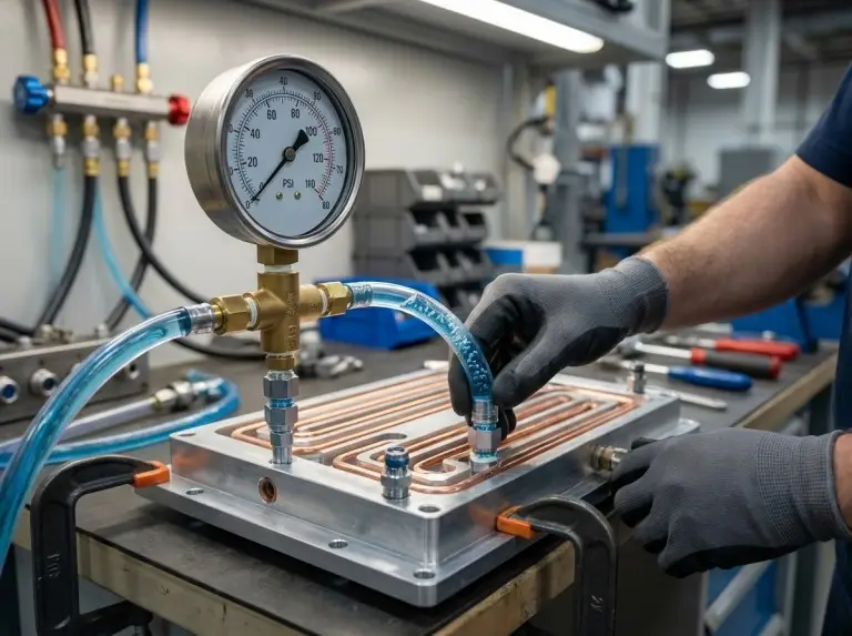
- Leak test acceptance criteria: set pressure level, test duration, and pass/fail limits before production starts. Do not define them after.
Hot spots do not only come from tube-to-plate gaps. Low flow at the heat source, uneven thermal interface material, base plate flatness error, and imbalanced flow in parallel circuits are just as common. Include all of them in pre-release verification.
Conclusion
Tubed cold plate selection comes down to three things: heat flux, coolant chemistry, and the thermal resistance budget set by the junction temperature limit. When all three fit within the range of pressed or press-lock construction, tubed cold plates are a reliable, cost-effective choice. When heat flux or temperature uniformity needs go beyond that range, brazed or machined designs are the better fit. Set that boundary with measured or modeled data — before committing to a construction method.
At Trumonytechs, we bring both material knowledge and manufacturing experience to this call. In serpentine tube designs for battery modules, tube routing cannot come from a standard layout. Pass positions must map to the actual inter-cell thermal load before the design is released. In high heat flux work — inverters, IGBT assemblies — the most common cause of redesign cycles is a construction method chosen before the thermal resistance requirement was confirmed. We treat tube material, attachment method, flow path routing, epoxy spec, and leak test criteria as separate verification items, not a single sign-off. That is how we stop that pattern before it starts.
To move forward, send us your component heat load, max junction temperature, available flow rate, coolant spec, and mounting geometry at the start of scope definition. With those inputs, we align the cold plate design to your application — or tell you where a different technology is the better fit.
FAQ
What is the thermal resistance range of a tubed cold plate?
It depends on tube diameter, pass count, attachment method, flow rate, and heat source footprint. Evaluate against your project parameters. Do not use typical published ranges as a substitute.
Can copper tubes be used with deionized water?
Yes, in some loop designs — but only with validated loop metallurgy, dissolved-gas control, water chemistry, and a clear maintenance plan. In mixed-metal loops or systems without active water quality control, copper ion leaching and deposit risk go up. Check this during design review.
How does tube attachment method affect leak risk?
Press-fit and press-lock quality matters for thermal contact and robustness. But leak integrity comes from tube continuity, end connections, fittings, and pressure-cycle durability. These are separate checks. Verify both before system integration.
When should a tubed cold plate be replaced with a brazed one?
When tubed construction cannot meet the thermal resistance target at the available flow rate and plate area. You need the heat load, max surface temperature, footprint, and coolant conditions to make that call. For alternative high-performance options, see our overview of microchannel cold plates. Do it at drawing review — not after the prototype fails.
Are turbulator inserts used in tubed cold plates?
They are an option in some custom circuits. They improve heat transfer by breaking up the fluid boundary layer, but they raise pressure drop. They are not standard in most commercial tubed cold plates. Check them against the pump curve and pressure budget before specifying.
