
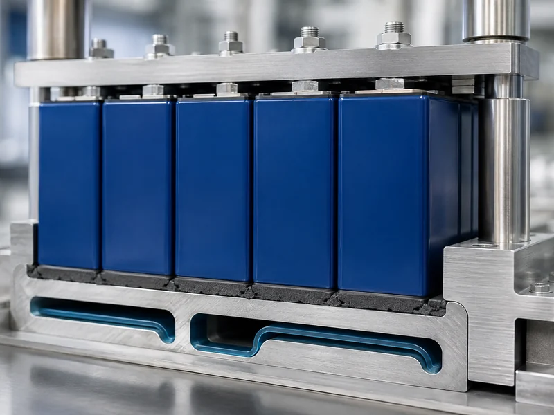
Compression is what turns a thermal interface material from a datasheet conductivity number into the contact resistance a battery pack actually runs at. A gap filler rated at several W/m·K delivers little of that rating until it is squeezed enough to wet both surfaces and push the trapped air out of the joint. In an EV or energy-storage pack, that squeeze happens between cells or modules and a cold plate. It has to work under real assembly tolerances and under real limits on how hard you can press a cell can or a circuit board. This article covers what compression does thermally, how compression ratio, compression force, and deflection differ, why more compression stops helping and starts hurting, and how to set a target for a cell-to-cold-plate gap. It does not cover specific product selection or the design of the liquid-cooling loop itself.
What Compression Does to a Thermal Interface Material
Compression lowers a joint’s thermal resistance mainly by improving real contact and displacing the air trapped at the interface, and by setting the bond-line thickness the joint finally holds. Still air conducts heat at only about 0.025 W/m·K, so any pocket of trapped air behaves like a local insulator in series with the conductive path. Pressing the interface material into the surface texture collapses those pockets and replaces them with a filler that conducts one to two orders of magnitude better. Compressible thermal management materials earn most of their measured gain this way. The drop in joint thermal resistance comes from removing that trapped air under representative pressure and bond-line thickness, not from the filler’s bulk conductivity number. Whether a material’s effective conductivity itself shifts with pressure depends on the specific product and its own test curve.
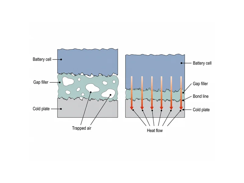
Real mating surfaces are never as flat or as parallel as a drawing implies. Machining marks, warp, plating buildup, and component-height variation leave a gap that changes across the joint, and the two solids only touch at a small fraction of their apparent contact area. A compressible interface material conforms into that varying gap. It carries heat across the regions where the solids never actually meet.
Battery packs make this harder than a single chip on a heat sink because the surfaces on both sides of the joint are uncooperative. A prismatic can, a pouch, or a module face sits against a cold plate whose flatness is set by its own manufacturing route, and the acceptable clamping load is bounded by what the cell and its fixturing can take. Understanding how compression sets the heat path is the starting point for matching thermal interface materials for batteries to a specific pack. A datasheet conductivity figure does not, on its own, tell you the thermal resistance the assembled joint will hold.
Compression Ratio, Force, and Deflection Are Not the Same Variable
Compression ratio, compression force, and deflection describe different things, and mixing them is a common source of confusion in a specification. Compression ratio is the fraction of thickness removed. You calculate it as the original thickness minus the compressed thickness, divided by the original thickness, and express it as a percent. It is a geometric target that says how far the material is squeezed. On its own it says nothing about how hard you have to push to get there.
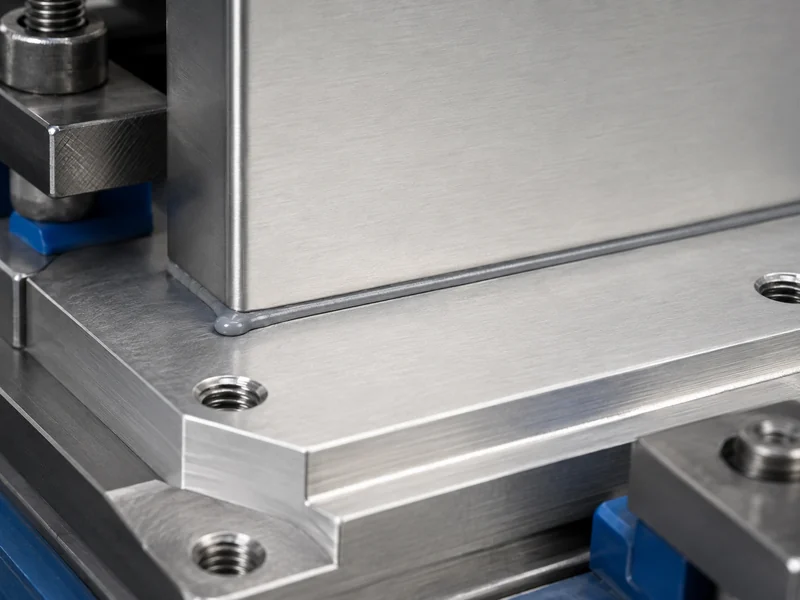
Compression force is the load required to reach a given deflection, and it depends on the material’s stiffness, its thickness, and the contact area. Published data often shows this as a compression-force-versus-deflection curve, because the force needed climbs non-linearly as the material is squeezed further. A softer, lower-modulus filler reaches the same compression ratio at a lower force. That matters directly when the load falls on a battery cell or a populated board, not on a rigid casting. When a joint also has to satisfy a target gap pad thermal conductivity, the force needed to seat that pad becomes part of the mechanical budget, not a detail to sort out later.
Hardness ties the two together but does not replace either. Soft gap fillers are frequently specified on a Shore 00 scale, because they are far too compliant to register meaningfully on harder durometer scales. A lower hardness generally means a lower compression force at a given deflection, which is why conformable fillers are chosen for uneven or fragile assemblies. Even so, the actual force still has to be read from the material’s own curve at the thickness and area you are using.
Why More Compression Is Not Always Better
More compression helps quickly at first and then stops paying off, so treating it as a dial to turn up is a mistake. The steep part of the benefit comes early, as the first increments of compression collapse the air voids and establish real contact. Past that, additional squeeze thins the bond line only slightly while the required force keeps rising, so the thermal return per extra newton of load shrinks. Published compression targets vary by material and supplier and do not settle on one figure. Some silicone gap fillers are cited around 15 to 20 percent, others in a 20 to 40 percent band, and some formulations are rated to compress considerably more. Treat any such number as specific to one product. Confirm the target against that part’s own datasheet and compression curve at your thickness, area, and load, not by porting a figure between products.
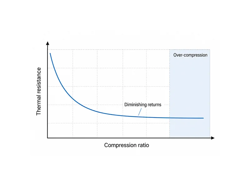
Over-compression is a reliability problem, not only a case of diminishing returns. Pushing a filler past its intended range can transmit excessive mechanical stress into whatever sits behind the joint. In a pack that can mean bowing a circuit board, loading a cell can beyond what its fixturing allows, or cracking a rigid substrate. The load that optimizes heat transfer and the load that threatens the components are not always far apart. Check the thermal-performance window and the mechanical limit of the weakest element in the stack separately, and let the tighter of the two set the target.
Long-term behavior under compression matters as much as the initial number. Interface materials can take a compression set, meaning they do not fully recover thickness after being held compressed. Some dispensed fillers can also be pushed out of the joint over thermal cycling, depending on the formulation and cure state, if the joint pumps as it heats and cools. Because those effects show up over the pack’s life, the thermal resistance that matters is the one under sustained, in-service compression, not a free-state datasheet value. Steady-state thermal resistance is characterized under load with a method such as ASTM D5470 at a stated pressure and bond-line thickness. Compression set, pump-out, and how much thermal performance is retained after cycling are separate durability questions, verified on their own rather than inferred from a single steady-state measurement.
Setting a Compression Target for Cell-to-Cold-Plate Gaps
Setting a compression target starts with the gap, not with the material, because the material only has to absorb whatever gap variation the assembly actually presents. Measure or estimate the distribution of gaps across the joint. Include the worst-case maximum from tolerance stack-up and the minimum where surfaces come closest. A filler has to stay in useful contact at the largest gap while not being crushed past its limit at the smallest. That spread, not any nominal dimension, sets how much compliance the material needs.
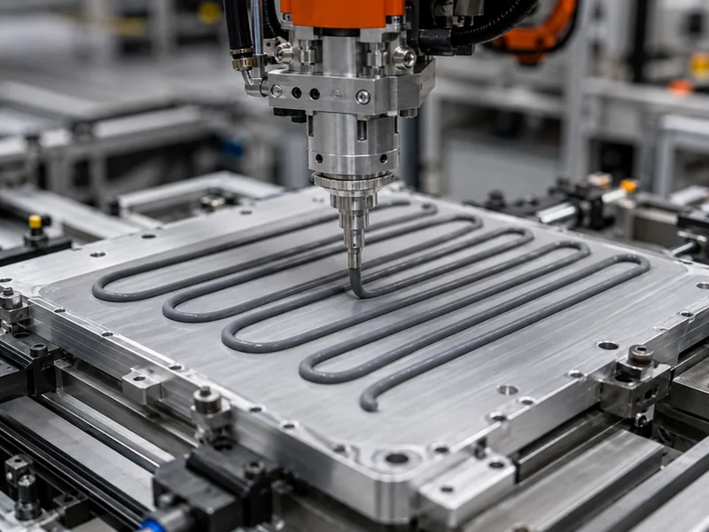
Flatness and the choice between a pre-formed pad and a cure-in-place gap filler follow from that spread. A die-cut gap pad suits joints where the gap is fairly uniform and repeatable. A dispensed, cure-in-place gap filler conforms to larger or less predictable variation without forcing a high seating load across the whole face. This trade-off is one of the core decisions in choosing the right thermal interface material for your application. It interacts directly with the compression target, because a stiffer pad at high compression can load fragile hardware that a softer dispensed material would not.
Assembly method and electrical requirements close out the target. Where a line dispenses filler at volume, that route can automate cleanly and absorb part-to-part variation without hand-fitted shims, which is a process factor to weigh, not an automatic default. The interface may also need to hold off voltage, which constrains the filler chemistry and the minimum material left in the thinnest part of the joint. Once those constraints are fixed, verify the design the way it will run. Confirm the compression force at nominal and worst-case gaps against what the cells and board can take, and confirm the resulting thermal resistance under that compression, not at free thickness.
Compression as a Bounded Design Variable
Compression is best read as a bounded variable. It is useful up to the point where the joint is wetted and the air is gone, and counterproductive beyond it. The core judgment a battery-pack engineer should carry away is one of order. Fix the gap distribution and the acceptable mechanical load first. Then pick a material soft enough to reach useful contact within that load. Only then settle on a compression ratio and the method used to verify thermal resistance under it. The number most often misread is the datasheet conductivity, which describes the bulk material and not the compressed joint that actually determines pack temperatures.
Where a joint has to reconcile an awkward gap spread with a low allowable clamping load, the result turns on the match between interface material, cell format, and cold-plate flatness. A single fixed compression percentage does not decide it. That pairing of interface material and cold plate sits at the center of Trumonytechs’ cell-to-coolant thermal work. Getting the match right is what keeps the heat path honest from the cell to the coolant.
FAQ
How much should I compress a thermal gap pad without cracking a cell or die?
Compress only as far as needed to close the air gaps and reach steady contact, then stop. The load that optimizes heat transfer can sit close to the load that damages fragile parts. The safe limit is set by the weakest mechanical element behind the joint — a cell can, a substrate, or a board. Check the compression force at the smallest expected gap against what that part can take. Published percentage ranges are a starting point, not a target to maximize, and the real limit comes from the mechanical budget of your specific stack.
Does more compression always lower thermal resistance in a battery pack TIM?
More compression lowers thermal resistance sharply at first and then delivers very little, so it is not a linear improvement. The early squeeze collapses the insulating air voids and builds real contact area, which is where most of the gain lives. Further compression only thins the bond line slightly while the required force keeps climbing. Past the useful range the added load buys almost no thermal benefit and starts risking mechanical damage and long-term compression set.
Should I use a gap pad or a cure-in-place gap filler for uneven cell-to-cold-plate gaps?
Choose based on how much the gap varies across the joint and how much load the parts tolerate, not on a default preference. A pre-formed gap pad suits fairly uniform, repeatable gaps and simple assembly. A dispensed, cure-in-place gap filler conforms to larger or less predictable variation without forcing a high seating load across the whole face. Where a line dispenses at volume, that route can also absorb part-to-part tolerance without hand-fitted shims, which is a process factor to weigh alongside the thermal and mechanical ones.
How do I keep gap filler compression force from bowing the PCB or stressing cells?
Control the force by choosing a softer, lower-modulus filler and by sizing the compression to the worst-case minimum gap, where the force peaks. A lower-hardness material reaches the same compression ratio at a lower load, which reduces what is transmitted into a board or a cell. Confirm the force at the tightest gap in the tolerance stack, not only at the nominal gap. Verify it against the mechanical limits of the parts behind the joint before committing the design.
Further Reading
- Properties of Thermal Interface Materials: Gap Fillers — a manufacturer technical white paper on how compressible gap fillers conform to surfaces and where their conductivity range comes from.
- ASTM D5470 Standard Test Method for Thermal Transmission Properties of Thermally Conductive Electrical Insulation Materials — the standard behind the under-load, steady-state thermal-resistance figures this article tells you to verify at a stated pressure and bond-line thickness.
- Thermal Interface Materials: From Fundamental Research to Applications — a peer-reviewed review that separates a joint’s bulk resistance from its contact resistance, the same split the compression discussion here depends on.
Related Articles
- Guide To Thermal Interface Materials — a plain-language primer on what TIMs are, the main material types, and how to pick one, for readers who want the wider context behind compression.
- Innovations in TIMs for Enhanced Thermal Management of Electronics — explains how TIMs fill the gap between heat sources and heat sinks, extending the gap-filling mechanism this article relies on.
- Conductive vs Non-Conductive Thermal Paste: A Selection Guide — helps readers separate thermal from electrical conductivity, which matters when the joint also has to hold off voltage.
- How Does Thermal Gel Work? — describes how a dispensed gel fills microscopic surface gaps, a close cousin of the cure-in-place fillers discussed here.
- How Often To Replace Thermal Paste? — covers how interface materials degrade over time, useful background for the compression-set and pump-out durability points.