
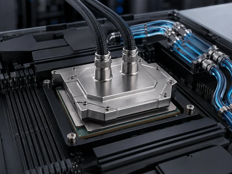
DLC cooling is direct liquid cooling: coolant runs through a cold plate bolted straight onto a processor, so heat leaves at its source instead of warming the room air. In cold-plate DLC the liquid stays sealed inside the plate and loop. It never touches the silicon, the board, or the connectors. Server cooling vendors generally report that this approach captures roughly 60–80% of a server’s heat at the chip, with air handling the remaining share. That capture ratio is why direct liquid cooling is now a mainstream approach for dense AI and high-performance computing (HPC) racks, where air alone runs short of headroom.
The search term points at data-center hardware, but the physics underneath is the same chip-to-coolant heat path that governs a battery cold plate. How flat is the contact interface? How well does the thermal interface material (TIM) fill the gap? How do the internal channels trade heat transfer against pressure drop, and does the coolant chemistry match the wetted materials? Those questions carry straight into EV and energy-storage (ESS) pack cooling. What does not carry over is the server-side system architecture — facility chilled-water plant sizing, CDU-to-building heat rejection, rack-density economics, and GPU TDP ceilings — because those depend on the deployment and the datasheet, not on the pack. This article stays with the transferable layer and marks where a server judgment should not be read onto a battery pack.
What Is DLC Cooling?
Bring the coolant to the hottest components, not the air around them: that is the whole idea behind DLC. The technology also goes by direct-to-chip (D2C) cooling or cold-plate cooling, and all three names describe one mechanism. A cold plate mounts against the CPU or GPU package, and a closed loop carries the absorbed heat away. Liquids move heat far more effectively than air because they are denser and hold more energy per unit volume, so the same thermal load leaves the rack through a much smaller path.
What matters for an engineer is *where* the heat is removed. Air cooling pulls heat off a heatsink and pushes it into the room, where it eventually reaches a CRAC or CRAH unit. Direct liquid cooling intercepts most of that heat at the package before it becomes a room-air problem. That shift lets a rack carry far more compute in the same footprint. It is also why accelerated-AI data centers turn to cold plate cooling solutions to add density beyond what their air systems handle.
How Direct Liquid Cooling Works
A direct liquid cooling loop moves heat through four linked stages: chip, cold plate, coolant loop, and heat rejection. The processor passes heat across a thin thermal interface material (TIM) into the cold plate. Coolant flowing through internal channels absorbs that heat. The warmed coolant travels to a coolant distribution unit (CDU), and the CDU rejects the heat to either facility water or air. Every stage adds thermal resistance, so the design goal is to keep each interface in that chain as low-resistance as it can be.

The CDU is the boundary between the server loop and the building, and it comes in two common configurations. A liquid-to-liquid (L2L) CDU hands heat to a facility water loop, which suits large deployments that already have chilled or warm water. A liquid-to-air (L2A) CDU rejects heat to room air through a heat exchanger and fans, which is easier to retrofit into a hall with no plumbing. The choice depends on whether facility water is available and how much rack density the site targets, so settle the CDU type before the cold plate and manifold layout are locked. This CDU-and-facility layer is exactly the part that does not transfer to a battery pack, where the vehicle or enclosure sets heat rejection, not a data hall.
Air never fully leaves the picture. Memory, drives, network cards, and voltage regulators still shed heat that no chip cold plate touches. Most real deployments are therefore hybrid: liquid at the hottest components, a smaller air path for everything else. Treating DLC as “liquid only” is a common planning mistake. The practical question is how to split the load, not whether air is still needed.
Single-Phase vs Two-Phase Direct-to-Chip Cooling
Whether the coolant changes state is the single difference that separates single-phase from two-phase DLC, and it drives cost, complexity, and how much heat the plate can move. In single-phase DLC the coolant stays liquid the whole way through the plate — typically a water-glycol mixture — and it carries heat away by warming up. In two-phase DLC the coolant boils inside the plate and condenses downstream, using the latent heat of vaporization to absorb more energy for a smaller temperature rise. The fluid is usually a dielectric or a refrigerant, not water.
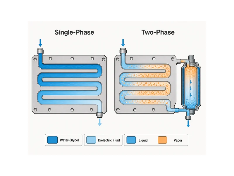
Single-phase is the established, simpler approach for many current deployments, but it still has to be engineered against real failure modes. Higher flow rates raise the risk of erosion corrosion inside channels and fittings over time, and any water-based loop carries leak consequences near live hardware. Loop materials and coolant chemistry both need review before deployment. Two-phase can move very high heat fluxes with a flatter temperature profile, but it adds pressure, condensation, and fluid-handling complexity. It becomes the case to consider when thermal design power (TDP) climbs past what single-phase can hold at an acceptable temperature rise. Before you trust a published flow or wattage figure, verify the coolant type, flow rate, and TDP ceiling against the specific plate and fluid you plan to use.
DLC Compared With Immersion and Hybrid Air Cooling
Direct-to-chip is only one liquid method, and picking among them comes down to how much heat you want liquid to carry. Alongside D2C, the main options are immersion cooling, where whole boards sit in a dielectric bath; rear-door heat exchangers, which cool exhaust air at the rack door; and liquid-to-air units that bring liquid close to the rack without plumbing the building. Each intercepts heat at a different point in the path, so they trade off retrofit effort, serviceability, and how high a density they can support.
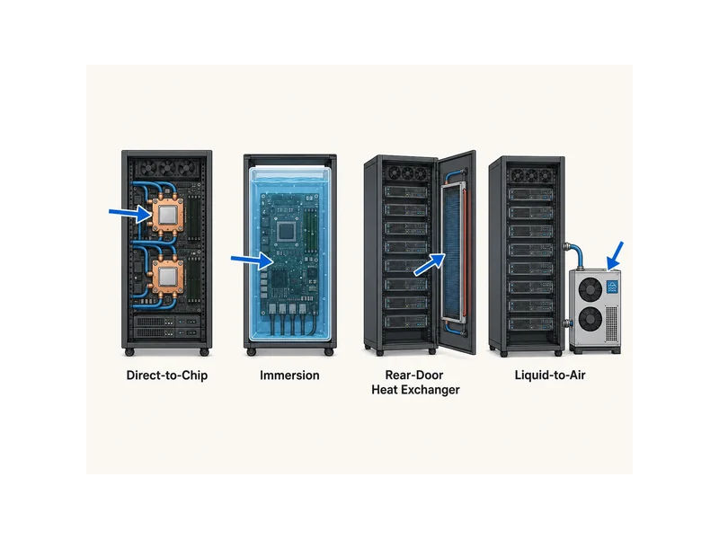
Direct-to-chip and immersion sit at opposite ends of that spectrum. D2C keeps servers serviceable and reuses much of a standard rack workflow while liquid-cooling only the hottest parts. That makes it the more incremental step for an operator adding density to an existing hall. Immersion removes air almost entirely but changes maintenance, fluids, and rack format wholesale. For teams comparing plate-based options, the differences in channel geometry and construction matter as much as the cooling category. A battery engineer faces the same distinction when matching a plate to a cell layout rather than to a server board.
Cold Plate Design in the Chip-to-Coolant Heat Path
The cold plate is where a DLC system succeeds or fails, because it owns the two interfaces that usually dominate thermal resistance in the loop. Heat has to cross from the chip lid into the plate through a thin, even layer of TIM, then from the plate wall into the moving coolant through the internal channels. If the plate is not flat where it meets the package, or the mounting pressure is uneven, the TIM gap grows and thermal resistance climbs no matter how cold the incoming coolant is. Flatness, gap control, and mounting force therefore belong on the acceptance checklist for every plate.
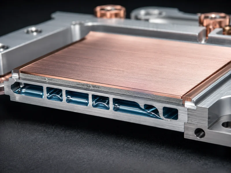
Channel design carries the second half of the job. Channel geometry, wall thickness, and flow layout set how much heat the plate pulls into the coolant and how much pumping pressure the loop pays for it — the central trade in any cold plate design for thermal management. Higher density and higher TDP push toward finer internal structures. But finer channels raise pressure drop and can concentrate flow velocity that accelerates erosion, so the plate has to be matched to the target flow rate, not maximized in isolation.
Getting those interfaces right is application-specific work, not a catalog pick, especially when a battery pack or a server rack mixes formats, gap tolerances, and assembly stresses. That is the premise behind custom cold plate solutions: the contact interface, channel layout, and coolant path are designed to the load instead of forcing the load onto a generic plate. The engineering checks are shared across applications — confirm flatness and mounting pressure, match channels to flow, and check materials against the coolant chemistry — but the load itself is not. A battery module’s gap tolerances, cell format, and structural bonding set different targets than an AI accelerator, and those pack-specific constraints, not the server numbers, should drive a battery cold plate.
Conclusion
Read DLC as three separate decisions and it stops blurring: the cooling category (direct-to-chip, immersion, hybrid), the coolant behavior (single-phase versus two-phase), and the hardware that does the work (the cold plate and its interfaces). For a battery thermal team, only the last one transfers cleanly — the contact interface, TIM gap, and channel-to-flow matching are the same physics whether the heat comes from a GPU or a cell. The server-side layers — the CDU, facility water, and rack-density targets — stay on the data-center side of the boundary. So the useful verification order is fixed: confirm flatness and mounting pressure first, match channels to the flow you actually run, then check materials against your coolant chemistry, and size the load from your own pack, not from a server spec sheet.
FAQ
Do I still need air cooling if I deploy direct-to-chip liquid cooling?
Yes. Most direct-to-chip deployments stay hybrid, not liquid-only. The cold plate captures the majority of heat at the CPU and GPU, but memory, drives, network cards, and power components still shed heat that no chip plate touches, so a smaller air path handles that remainder. Plan the liquid and air shares together, not on the assumption that liquid removes everything.
Single-phase or two-phase direct-to-chip for high-TDP GPUs?
Single-phase handles many current high-TDP GPUs and is the simpler system to deploy, so it is a common starting point. Two-phase becomes worth its added pressure and fluid-handling complexity mainly when thermal design power climbs past what single-phase can hold at an acceptable temperature rise. Decide by verifying the TDP ceiling and coolant type against the specific plate, not by a general rule.
How many kW per rack can direct liquid cooling support versus air?
Direct liquid cooling supports substantially higher rack density than air, which is its main reason to exist. Vendor figures for both air and liquid vary widely with hardware and facility design, so treat any single number as directional and size density against your actual servers, CDU, and coolant loop. The dependable takeaway is the direction: liquid removes heat at the source, so it enables far denser racks.
Does the coolant actually touch the chip in cold-plate DLC?
No. In cold-plate DLC the coolant stays sealed inside the plate and loop and never contacts the chip, board, or connectors. Heat crosses from the chip into the plate through a thermal interface material, and the liquid only flows through channels inside the plate. That containment is a core design feature, which is why leak-path materials and fittings still warrant review even though the fluid is isolated.
Further Reading
- Direct-to-chip cooling glossary — A neutral glossary entry defining direct-to-chip cooling, CDU configurations, and single- versus two-phase operation, backing the mechanism and CDU sections above.
- 5 Misunderstood Facts About Direct-to-Chip Liquid Cooling — Explains why deployments stay hybrid and why coolant never contacts the hardware, supporting the “still need air” and containment points.
Related Articles
- Data Center Chillers: Choosing Between Air-Cooled and Water-Cooled Plants — Shows where the chiller and facility water plant sit downstream of the CDU, and how load, climate, and water availability pick the plant type.
- What is Heat Transfer? — Breaks down conduction, convection, and radiation, the mechanisms behind every cold-plate and coolant heat path in this article.
- What Is a Tubed Cold Plate? — Explains how tubing bonded into an aluminum base moves heat, a different plate construction to weigh against machined channels.
- How Does Heat Pipe Cooling Work and When Should You Use It? — Covers a passive two-phase alternative that moves heat without a pump, useful context when comparing coolant behaviors.
- What Are the Different Types of Cooling Plates — Compares cold-plate types by channel design and construction, the plate-level distinction this article flags for battery-versus-server choices.
