
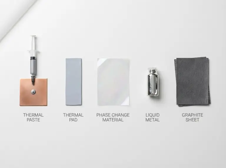
Choosing a thermal paste alternative comes down to five things: interface gap, thermal load, assembly process, electrical insulation needs, and pump-out risk. Texture or appearance has nothing to do with it.
Four categories of engineered thermal interface materials can replace thermal paste. Each one involves trade-offs. None of them should go into production without application-specific testing first.
This guide is written for engineers and procurement teams working in electronics manufacturing, industrial equipment, or field maintenance. It does not cover household substitutes. Those materials fail under sustained thermal cycling and have no place in engineered thermal management.
What Any Thermal Paste Alternative Must Replicate
Thermal paste does two things at once. It fills the air voids created by microscopic surface irregularities. It also holds a low-resistance conductive path between the heat source and heat sink across the device’s operating life. Any alternative must do both — not just one.
Four criteria define a qualified engineered replacement. First, it must conform to surface irregularities well enough to eliminate trapped air under the available clamping pressure. Second, it must deliver enough thermal conductivity for the component’s power density. That depends on interface area, bond line thickness, and heat flux — not on the conductivity number alone. Third, it must stay dimensionally and chemically stable across the application’s full temperature and cycling profile. Fourth, it must meet the electrical insulation requirements of the interface — these vary significantly between CPU die applications and power module designs.
One rule applies to all alternatives: supplier conductivity figures are not comparable unless they were measured under the same test method and contact pressure. Always ask for the test method, bond line thickness, and contact pressure alongside the stated value.
When Thermal Paste Is Still the Right Answer
Not every situation calls for a switch. Thermal paste is still the right choice when the interface gap is below 0.2 mm, surface finish is well controlled, assembly volume is low enough to manage how to apply thermal paste manually, and power density is within what standard paste can handle. Switching in these conditions adds qualification cost without any real benefit.
A switch makes sense in these situations: the gap is too large for paste to fill uniformly, the assembly process needs robotic placement or zero cure time, field maintenance makes paste cleanup impractical between service cycles, pump-out is a documented reliability risk, or the paste formulation cannot meet the insulation requirement.
Why Paste Pump-Out Matters for Alternative Selection
Pump-out is one of the most common engineering reasons to move away from thermal paste. Understanding how it works clarifies which alternatives actually solve the problem.
During thermal cycling, the heat source and heat sink expand and contract at different rates. This relative movement pushes paste from the center of the interface toward the edges over time. Thermal resistance rises — with no visible sign at the assembly level.
Pump-out risk is highest when die area is large, temperature swings between idle and load are wide, and the mounting allows lateral movement during cycling. Teams that run initial thermal validation without accounting for pump-out often pass qualification, then see thermal resistance climb over the product lifecycle. That failure is hard to diagnose without disassembly. Identifying pump-out risk upfront — before selecting a material — is the right starting point.

Engineered Thermal Paste Alternatives and Their Application Profiles
Thermal Pads (Silicone and Non-Silicone)
Thermal pads are pre-formed solid sheets. Most are silicone elastomer filled with ceramic or metallic oxide. Supplier-reported conductivity for standard grades typically runs from 1 to 12 W/m·K; higher-loaded formulations reach 15 W/m·K. Thickness options generally span 0.2 mm to 5 mm, which makes them practical for larger or variable gaps where paste application is uneven.
Because pads are solid at room temperature, they cannot conform to microscopic surface irregularities the way paste does under pressure. This means higher interfacial thermal resistance for the same gap — especially on surfaces rougher than approximately Ra 1.6 µm. The gap in performance narrows as interface thickness increases, because height-variation tolerance becomes more valuable than microscopic conformity at larger gaps.
Thermal pads suit high-volume assembly well. Pre-cut formats remove manual application variability, support robotic placement, and allow immediate part handling with no cure time. Pads also resist pump-out by design — their solid form does not migrate under cycling. Some formats are reusable, which reduces material cost where rework is frequent. Silicone-free thermal interface materials are available for environments sensitive to siloxane outgassing, such as optical, medical, and precision sensor applications.
Phase Change Materials
Phase change materials start as solid sheets. They transition to a semi-liquid state at operating temperature — typically between 45°C and 70°C, depending on formulation. In the liquid phase, PCMs conform to the interface surface comparably to paste and fill microscopic voids under modest clamping pressure. Supplier-reported conductivity typically falls between 3 and 8.5 W/m·K. Actual performance depends on how fully the material flows at the real interface temperature and pressure.
PCMs are the most direct functional alternative to paste when pump-out is a known reliability risk. They re-solidify when the device cools and re-liquefy on the next power cycle. Unlike paste, they do not migrate out of the interface over time. This makes them a strong fit for long-lifecycle applications where reapplication during field service is not feasible.
One process point matters here: PCMs need a burn-in period. The material requires multiple thermal cycles above its phase transition temperature before it fully wets the interface and reaches stable minimum thermal resistance. Thermal validation must account for this. Measuring performance before enough cycles have completed gives a higher resistance reading than the material’s true steady-state capability.
Liquid Metal Thermal Compounds
Liquid metal compounds — primarily gallium-indium alloys — offer conductivity values well above conventional paste. Supplier figures typically range from 30 to 80 W/m·K, though actual performance depends heavily on bond line thickness and surface preparation. This makes liquid metal relevant for high-power-density components where standard paste cannot provide enough dissipation.
Two constraints are non-negotiable. Liquid metals conduct electricity, so any spread beyond the die boundary creates a short-circuit risk. They also react with aluminum surfaces through galvanic corrosion. Use requires confirmed copper or nickel-plated mating surfaces, controlled application to prevent lateral spread, and explicit risk sign-off before production.
Thermal Putty
Thermal putty sits between paste and solid pads. It conforms under light pressure to irregular contact surfaces without requiring precise spreading. It is not constrained by fixed thickness dimensions, so it can accommodate height differences across a single assembly. Supplier-reported conductivity for commercial thermal putty typically runs from 6 to 13 W/m·K depending on filler loading.
Thermal putty works well when multiple components of different heights share a common heat spreader, making uniform pad thickness impractical. It is generally not reusable after compression and should be replaced during rework.
Graphite Sheets (Supplementary Role Only)
Graphite sheets have very high in-plane conductivity — above 700 W/m·K laterally — but through-plane conductivity is typically only 5 to 10 W/m·K. That profile suits hotspot spreading, not direct component-to-heatsink conduction. Graphite sheets conduct electricity and cannot contact bare circuit elements. They work best as a supplementary layer within a thermal path that already includes another TIM, not as a standalone paste replacement.
Variables That Determine Which Alternative Fits
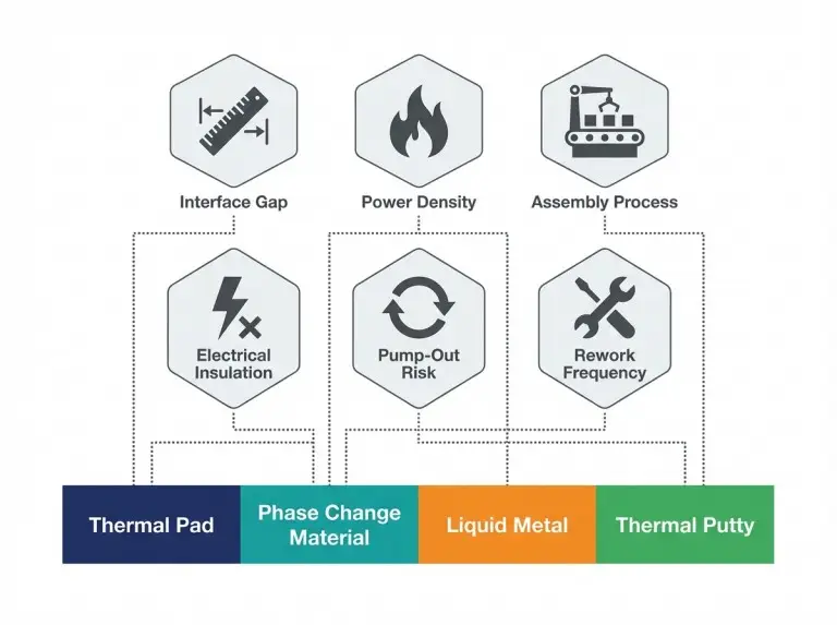
Six variables determine the right alternative. Thermal conductivity value alone is not enough.
- Interface gap thickness comes first. Thermal paste works best below approximately 0.2–0.3 mm. Above 0.5 mm, pads or PCMs are more appropriate. Thicker paste bond lines raise thermal resistance proportionally. Treat these thresholds as indicative and confirm them against the specific material’s BLT data.
- Pump-out risk determines whether PCM or pad formats are needed for long-term reliability. Large die area, wide temperature swings, and long product life all raise this risk. Evaluate it explicitly rather than assuming paste will hold.
- Power density at the interface sets the conductivity floor. Standard pads at 6–8 W/m·K often cover memory chips and low-power ICs. High-power processors, power MOSFETs, and IGBT modules typically need higher conductivity or PCM-level conformity.
- Assembly process shapes what is viable. Automated lines favor pre-cut pad formats. Manual or field assembly favors materials that do not need precise spreading technique.
- Reusability and rework frequency affect total material cost over time. Reusable pad formats and PCMs reduce the cleaning and reapplication burden compared to paste replacement cycles.
- Electrical insulation requirement rules out liquid metal from any geometry where spread beyond the die is possible. It also restricts high metallic-loaded formulations where migration could create conductivity paths.
When comparing candidates, use thermal resistance per unit area: R″ = BLT ÷ k. A 2 mm pad at 10 W/m·K has higher effective resistance than a 0.1 mm paste layer at 5 W/m·K. Always evaluate R″ alongside the conductivity figure.
Verification Before Committing to a Thermal Paste Alternative
Datasheet comparison narrows the list. It does not finish the qualification. Three steps apply before committing to production.
First, measure bond line thickness after assembly. Confirm the material is compressed to its specified performance range. A BLT outside that range is the most common reason thermal resistance comes in higher than expected when switching from paste to a pad format.
Second, monitor junction temperature under representative load. Compare it against the thermal design prediction. If the gap exceeds the component’s thermal headroom, review material selection, compression force, and surface preparation before moving forward.
Third, for PCM alternatives, complete the required burn-in cycles before recording final performance data. Measuring resistance before the material has fully wetted the interface understates the alternative’s actual steady-state capability. It can lead to rejecting a material that would have performed correctly after proper conditioning.
Applications with extreme clamping pressures, highly irregular surfaces, vibration environments, or regulatory certification requirements need additional scope definition before material selection is finalized.
Conclusion
The right thermal paste alternative depends on gap geometry, pump-out risk, power density, assembly process, insulation requirements, and maintenance access. Datasheet review alone cannot answer the question — application-level validation always does.
Thermal pads suit high-volume assembly and larger gaps. PCMs suit long-lifecycle applications that need both pump-out resistance and paste-level conformity. Liquid metal suits extreme power density where geometry is tightly controlled. Thermal putty suits irregular or multi-height interfaces where neither paste nor fixed-thickness pads are practical.
At Trumonytechs, we work with engineering and procurement teams on TIM selection across industrial, power electronics, and thermal management applications. In our qualification work, the two most consistent sources of unexpected results when switching from paste are skipping PCM burn-in cycles and accepting a pad thickness that exceeds the actual interface gap. Both produce higher-than-expected thermal resistance readings. Both are often blamed on material quality when the real cause is application conditions. Confirming BLT, compression force, burn-in protocol, and surface condition before production prevents most of the post-qualification failures we see in switched designs.
If you are evaluating a thermal paste alternative for a specific design, share your interface geometry, power density, operating temperature range, and assembly process with our team. We can identify material candidates, clarify the validation steps needed, and flag where supplier data should be verified against your actual conditions before qualification closes.
FAQ
How do I verify that two suppliers’ conductivity figures are actually comparable?
Request the test method, contact pressure, and bond line thickness used during measurement. Transient methods routinely report higher values than ASTM D5470 because they undercount interface resistance. Without aligned test conditions, the numbers measure different things.
When does a thicker pad raise thermal resistance instead of lowering it?
When it exceeds the actual interface gap. Thickness fills gap — it does not improve conductivity. Specify pad thickness against measured gap data, not standard stock dimensions.
What should we confirm before switching from paste to a pad in production?
Three things: gap consistency across units, assembly pressure within the pad’s compression spec, and surface finish within its conformity tolerance. For silicone-based pads, also check whether adjacent process steps are siloxane-sensitive.
Is liquid metal practical for high-volume production?
Yes, but only with tight application controls and confirmed surface compatibility upfront. The electrical shorting risk from overspread makes it unsuitable where containment geometry cannot be held reliably across volume.
How does pump-out affect the paste-versus-PCM decision over a product’s life?
Paste pump-out is cumulative and silent — junction temperatures rise with no assembly-level indicator until the margin is gone. PCMs don’t migrate on cooling, so the failure mode doesn’t apply. The longer the product lifecycle and the more frequent the thermal cycling, the stronger the case for PCM.
