
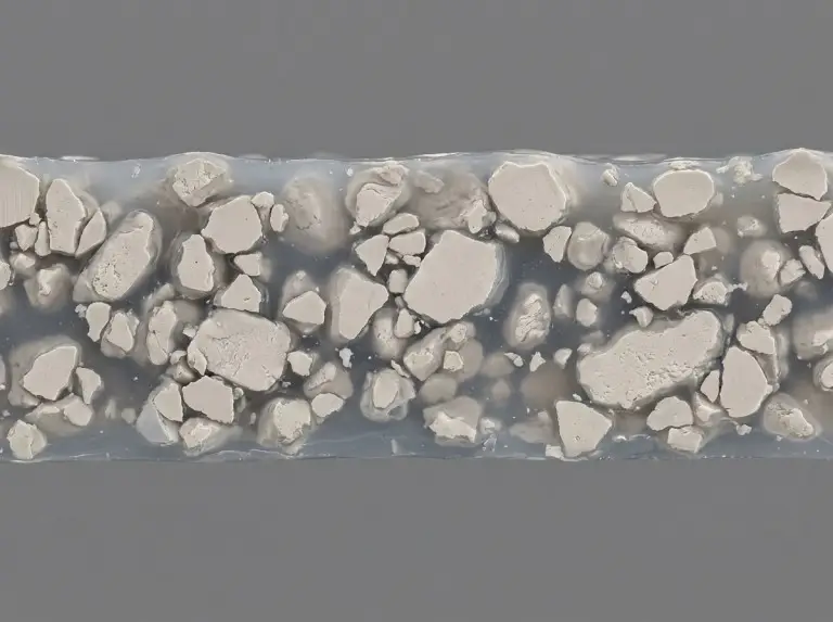
Thermal paste, thermal grease, and Thermal Interface Material (TIM) refer to the same engineered material class — this article uses all three terms interchangeably throughout.
Understanding what thermal paste is made of requires examining two co-dependent systems: the filler phase, which drives thermal conductivity, and the carrier matrix, which controls long-term mechanical and chemical stability. The core answer is this — thermal paste consists of thermally conductive filler particles suspended in a carrier base, where filler type, particle size, and loading concentration collectively determine conductivity, electrical safety, and service life.
The thermal conductivity values listed for individual filler materials throughout this article are intrinsic reference values for bulk polycrystalline material under standard room-temperature conditions. Actual formulation bulk conductivity depends on loading concentration, particle size distribution, and matrix interface resistance. Final performance requires measured data from the complete formulation per ASTM D5470 or equivalent. For regulated applications including medical devices and EV energy storage systems, request complete test reports from your supplier covering the applicable industry standard.
This article does not apply to phase-change materials, thermally conductive adhesives, or graphite sheet TIMs — those material classes involve distinct chemistry and selection criteria outside this scope.
Why Thermal Paste Conductivity Alone Falls Short
Thermal conductivity in a TIM formulation varies by filler type, loading concentration, and application environment — maximizing W/m·K alone produces a suboptimal design outcome in most engineering scenarios. This is a distinction we consistently apply in our formulation development work, where single-axis optimization regularly fails in real application validation.
Three performance axes govern every formulation decision:
- Thermal conductivity (W/m·K): How efficiently heat transfers through the bulk material.
- Dielectric strength (kV/mm): Whether the cured or uncured paste resists electrical leakage under operating voltage.
- Pump-out resistance: Whether the paste maintains gap-fill integrity through thermal cycling without migrating out of the interface.
These three axes trade against each other. Metallic fillers maximize conductivity but compromise dielectric strength. High filler loading increases conductivity but raises viscosity and worsens pump-out resistance under cycling. Understanding this three-axis trade-off is the prerequisite for reading every section that follows.
Filler Materials and Their Conductivity Trade-offs
Filler materials in a TIM formulation determine bulk thermal conductivity, electrical behavior, and particle morphology constraints — each filler category forces a distinct set of engineering compromises that no carrier modification can fully offset. Three categories cover the full design space — metallic, ceramic, and carbon-based — each representing a distinct set of types of thermal pastes with its own conductivity ceiling, electrical behavior, and carrier compatibility constraints.
When to Choose Metallic Fillers
Metallic fillers deliver the highest intrinsic thermal conductivity values available across filler categories. Silver’s intrinsic conductivity — roughly four hundred watts per meter-kelvin at room temperature — makes it the highest-performing metallic filler available (420 W/m·K, bulk polycrystalline, room temperature). Copper (Cu) reaches approximately 400 W/m·K under the same conditions. Aluminum (Al) reaches approximately 237 W/m·K. These values make metallic fillers the preferred choice where thermal performance is the dominant constraint and electrical exposure is controlled by design.
The trade-off is direct. Metallic fillers are electrically conductive. A TIM formulation using silver or copper filler will exhibit bulk electrical conductivity proportional to particle loading and network percolation. In exposed-pad packages, bare-die designs, or any configuration where paste migration reaches a voltage-carrying surface, metallic TIMs create leakage risk. The risk is not marginal — it is a disqualifying condition in most power electronics designs unless the interface geometry is fully enclosed and verified. Leakage current risk should be evaluated against the application voltage level — for systems above 48 V DC, a volume resistivity of at least 1 GΩ·cm is typically required — and verified per the applicable assembly qualification standard rather than inferred from bulk material data alone.
Aluminum-filled pastes occupy a middle position. Aluminum’s bulk conductivity is lower than silver or copper. Aluminum oxide forms naturally on particle surfaces during processing, which partially reduces bulk electrical conductivity at the formulation level — but this oxide layer is process-dependent and not a guaranteed isolation barrier, so aluminum-filled TIMs should not be treated as electrically safe by default.
Ceramic Fillers for Isolation
Ceramic fillers provide meaningful thermal conductivity combined with intrinsic electrical insulation. This combination makes ceramic-filled TIMs the dominant choice in power electronics, EV battery modules, and any application where dielectric strength is a specification requirement. These fillers are also the backbone of most silicone-free thermal interface solutions, which increasingly specify ceramic systems to eliminate both silicone contamination and electrical isolation risk simultaneously.
Three ceramic fillers cover most design scenarios:
| Ceramic Filler | Intrinsic Thermal Conductivity (approx.)* | Notes on Conditions | Dielectric Strength | Relative Cost |
|---|---|---|---|---|
| Aluminum Oxide (Al₂O₃) | ~30 W/m·K | Bulk polycrystalline, room temperature | High | Low |
| Zinc Oxide (ZnO) | ~25–29 W/m·K | Bulk polycrystalline, room temperature | Moderate–High | Low–Medium |
| Boron Nitride (BN) | Up to ~400 W/m·K (axial) | h-BN platelet, axial direction | High | High |
*Intrinsic values are standard reference values for bulk polycrystalline material at room temperature. Actual formulation bulk thermal conductivity depends on loading concentration, particle size distribution, and matrix interface resistance, and must be confirmed by complete-formulation testing per ASTM D5470 or equivalent. Formulation bulk conductivity is substantially lower than filler intrinsic values at all practical loading levels.
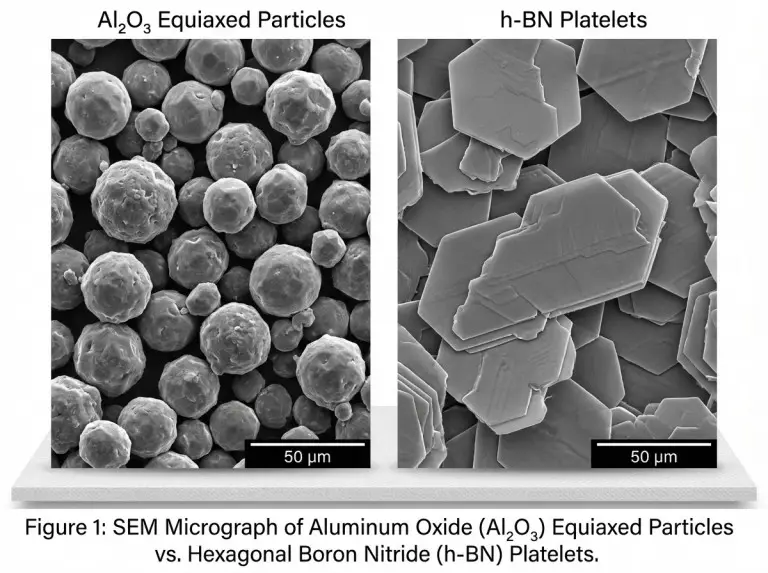
Aluminum oxide is the most widely used ceramic filler due to low cost and reliable dielectric performance. Zinc oxide offers comparable electrical isolation with slightly different morphology, making it useful in formulations that require specific rheological behavior. Boron nitride is structurally distinct — its platelet morphology provides significantly higher axial thermal conductivity than equiaxed ceramics at equivalent loading. The platelet geometry also allows higher packing density in multimodal distributions, which is a formulation advantage when conductivity targets exceed what Al₂O₃ or ZnO can deliver without excessive loading.
Carbon-Based Fillers and Thermal Anisotropy
When heat flux direction can be controlled by assembly geometry, carbon-based fillers offer thermal conductivity pathways that equiaxed ceramics cannot approach — graphite, CNTs, and graphene platelets all conduct heat efficiently along their basal or axial direction while remaining poor conductors perpendicular to it.
Individual CNTs exhibit theoretical axial thermal conductivity values reported above 3,000 W/m·K under idealized single-nanotube measurement conditions; in bulk formulations, realized conductivity is substantially lower due to interface resistance between tubes and matrix, random orientation distribution, and agglomeration defects — reported bulk formulation values typically fall in the range of tens to low hundreds of W/m·K depending on CNT quality, loading, and alignment. Graphene platelets carry similar anisotropy.
This anisotropy has two implications. First, orientation control during dispensing and curing determines whether the high-conductivity axis aligns with the heat transfer direction. Second, carbon-based fillers at sufficient loading exhibit measurable electrical conductivity, particularly along the high-conductivity axis. These fillers are best suited to applications where directional thermal management is designed into the assembly and where electrical isolation is provided structurally rather than by the TIM itself. Emerging power module and high-density electronics applications are where we see carbon-based TIMs applied with the most engineering discipline.
Which filler category a formulation uses determines its thermal ceiling — but the carrier matrix determines whether that ceiling holds after five years of thermal cycling.
Carrier Matrix Systems and Long-Term Stability
Long-term reliability in any TIM program depends more on carrier selection than on filler choice alone — the matrix governs oil bleed resistance, dispensing compatibility, and the service temperature ceiling that determines whether a formulation holds specification over a 10-year battery pack life. Filler selection cannot compensate for a carrier that degrades under the application’s thermal cycling profile.
Silicone Oil Base and Its Thermal Limits
Silicone-oil carriers are the most widely used TIM base due to low-temperature flexibility, oxidative stability up to approximately 150–200 °C (depending on polydimethylsiloxane molecular weight and formulation additives — supplier TGA data should be requested to confirm the specific upper limit for any given formulation), and compatibility with a broad range of fillers. Polydimethylsiloxane (PDMS) and its functional derivatives are the standard silicone base fluids.
Two risks are process-relevant. First, oil bleed — the migration of low-molecular-weight silicone fractions out of the filler network under thermal cycling or sustained elevated temperature. Oil bleed deposits silicone on adjacent surfaces, which causes adhesion failures in secondary bonding operations and can contaminate optical components or electrical contacts. Second, silicone vapor — at temperatures approaching the upper stability limit, volatile silicone species can deposit on connector contacts and relay surfaces. In automotive and aerospace applications, silicone contamination is a controlled risk requiring qualification testing, not a theoretical concern.
Non-Silicone and Hydrocarbon Carriers
Where silicone vapors are a disqualifying condition rather than a theoretical concern, synthetic hydrocarbon carriers — PAO, PIB, and other non-silicone bases — provide the stable, low-vapor-pressure alternative that automotive and optical system programs require. These carriers are specified in applications where silicone volatiles are disqualifying: certain automotive control modules, hard disk drive environments, and optical systems.
PAO carriers in particular offer good thermal stability, low vapor pressure, and compatibility with high-temperature filler systems. The trade-off is narrower formulation latitude. Non-silicone bases often have higher viscosity baselines and more limited low-temperature flow behavior than silicone counterparts. For EV battery pack applications with long service intervals and operating temperatures that cycle below 0 °C, carrier selection requires validation against the full temperature profile — not just the upper limit. We specify non-silicone bases for automotive TIM programs where silicone vapor contamination is explicitly excluded by the OEM requirement.
Carrier selection sets the stability boundary; the formulation parameters that follow — particle size, loading concentration, and size distribution — determine how much of the filler’s thermal potential actually translates into measured bulk conductivity.
Particle Size, Loading, and Multimodal Grading
Three controllable parameters — particle size, volume loading, and size grading — set the performance ceiling of any TIM formulation, and no single variable can be adjusted in isolation without shifting the other two.
Particle size determines packing geometry and interface contact area. Smaller particles (sub-micron range) maximize surface contact but raise viscosity sharply at equivalent loading. Larger particles (5–20 µm range) allow higher loading at lower viscosity but reduce packing uniformity in thin bond lines.
Volume loading concentration drives conductivity to a threshold. Below the percolation threshold — the concentration at which filler particles form a continuous thermal network — conductivity scales weakly with loading. For typical ceramic filler systems, this threshold falls in the range of approximately 35–45 volume percent; above this concentration, conductivity rises more steeply, then plateaus as matrix interfacial resistance limits further gains. Practical loading is additionally constrained by viscosity: above roughly two-thirds of the formulation by volume (approximately 65–70 volume percent in most ceramic formulations), viscosity increases prohibitively for dispensing-compatible processing.
Multimodal particle size grading resolves the loading-viscosity conflict. Mixing two or three distinct particle size fractions — typically combining a coarse fraction in the 10–20 µm range with a fine fraction in the 1–2 µm range — allows smaller particles to fill void space between larger ones, increasing packing density without increasing viscosity proportionally. Multimodal grading is precisely how high-conductivity formulations (above 6–8 W/m·K bulk) achieve dispensing-compatible viscosity. How well these parameters translate to field performance depends on thermal paste application methods and bond line control as much as formulation choice.
These parameters interact, and the design space requires iterative validation per ASTM D5470 for bulk conductivity and rheological testing for process compatibility.
That validation framework becomes the decision filter for the application-sector selection logic that follows.
TIM Selection by Application Sector
Application-sector TIM selection varies by temperature range, electrical isolation requirement, and dispensing process constraints — translating the filler-matrix framework into a workable decision path requires matching these three variables to the formulation space available.
| Application Sector | Temperature Range (typical)† | Electrical Isolation Requirement | Preferred Filler Class | Carrier Preference |
|---|---|---|---|---|
| EV Battery Pack | –30 °C to 85 °C (cell surface) | Required (cell-to-cell) | Ceramic (Al₂O₃, BN) | Non-silicone or low-bleed silicone |
| Power Modules (IGBT/SiC) | Up to 175 °C junction | Required | Ceramic (BN-dominant for conductivity) | High-stability silicone or PAO |
| Industrial Electronics | –20 °C to 125 °C | Application-dependent | Ceramic or metallic depending on isolation | Silicone |
†Temperature ranges are representative industrial reference values for the stated application sectors. Actual operating limits must be confirmed against OEM thermal management specifications and the applicable qualification standard — AEC-Q200 for automotive components, or the relevant IEC or UL standard for the end-use classification.
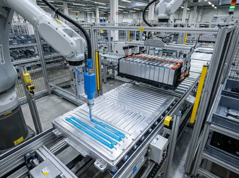
EV battery packs require electrical isolation between cells or between cells and cooling plates, eliminating metallic fillers from most positions. Thermal cycling depth is high, so pump-out resistance and oil bleed behavior over 10+ years drive carrier selection. We validate EV battery TIMs against multi-thousand-cycle thermal shock profiles before production release.
Power module applications — particularly SiC and IGBT modules operating above 150 °C — require both high conductivity and dielectric strength. BN-dominant ceramic formulations in high-stability carriers address this. Non-silicone carriers are increasingly specified by automotive OEMs for power module TIMs due to silicone contamination exclusions in module assembly environments.
Industrial electronics covers a broad temperature range with more variable isolation requirements. Metallic fillers remain viable in enclosed-interface geometries without exposed voltages. Ceramic fillers cover all isolation-required positions. Carrier selection is less constrained than in automotive, though long service life requirements in infrastructure electronics increasingly favor lower-bleed formulations. For a structured framework on choosing a thermal interface material across these sectors, carrier stability under the expected thermal cycling profile is the starting filter.
The questions most frequently raised in selection reviews — about metallic filler safety, ceramic filler trade-offs, and long-term carrier stability — are addressed directly below.
Conclusion
In our project experience across EV battery thermal management and power module programs, single-axis optimization — choosing the highest-conductivity option without validating dielectric strength, pump-out resistance, and carrier stability against the actual service life profile — has been a recurring source of TIM selection errors. The material chemistry described in this article provides the framework to avoid that failure mode and to read supplier datasheets with the specificity those decisions require.
If your application requires a tested, specification-grade solution, our thermal conductive grease line covers silicone-base and non-silicone formulations validated across the EV battery and power module sectors. We’re available to support filler and carrier selection for your specific thermal cycling profile and isolation requirement — reach out to discuss your program.
FAQ
Do metallic fillers make thermal paste electrically conductive in power electronics?
Metallic thermal paste fillers conduct electricity once particle loading passes the percolation threshold — the safety issue is not bulk conductivity in isolation, but whether paste migrates to voltage-carrying surfaces during thermal cycling. Fully enclosed, laterally constrained interfaces can use metallic TIMs safely if migration risk has been characterized. Exposed-pad packages or any geometry where squeeze-out reaches board traces require ceramic-filled alternatives; leakage risk must be verified per the applicable assembly qualification standard, not inferred from bulk material data.
How do aluminum oxide, zinc oxide, and boron nitride compare as ceramic fillers?
Al₂O₃ (~30 W/m·K intrinsic) is the standard choice for formulations where bulk conductivity below 4–5 W/m·K is acceptable and cost is a constraint. ZnO (~25–29 W/m·K) offers similar isolation with different particle morphology, which affects rheological behavior in high-loading formulations. BN platelet structure enables bulk conductivity above 6–8 W/m·K while maintaining dielectric strength, at a significant cost premium. All three values are filler reference figures; actual formulation conductivity requires ASTM D5470 testing.
What distinguishes silicone-base from non-silicone-base TIMs at high temperature?
Silicone-oil carriers hold up to approximately 150–200 °C, but above that range volatilize low-molecular-weight fractions onto adjacent surfaces — a qualification-level failure mode in automotive environments. PAO and synthetic hydrocarbon carriers exhibit lower vapor pressure, less oil bleed, and no silicone-specific contamination risk. Automotive and long-service-interval power electronics programs increasingly specify non-silicone bases, despite their narrower low-temperature processing range.
How do particle size and loading concentration affect formulation thermal conductivity?
Below the percolation threshold (~35–45 vol% for ceramic fillers), additional filler adds little conductivity; once exceeded, conductivity rises steeply but plateaus as matrix interfacial resistance becomes the limiting factor. Sub-micron particles raise viscosity sharply at equivalent loading; larger particles in the 10–20 µm range allow higher loading at lower viscosity. Multimodal distributions — mixing coarse and fine fractions — resolve this conflict, which is why formulations above 6–8 W/m·K bulk routinely use bimodal or trimodal size distributions.
