
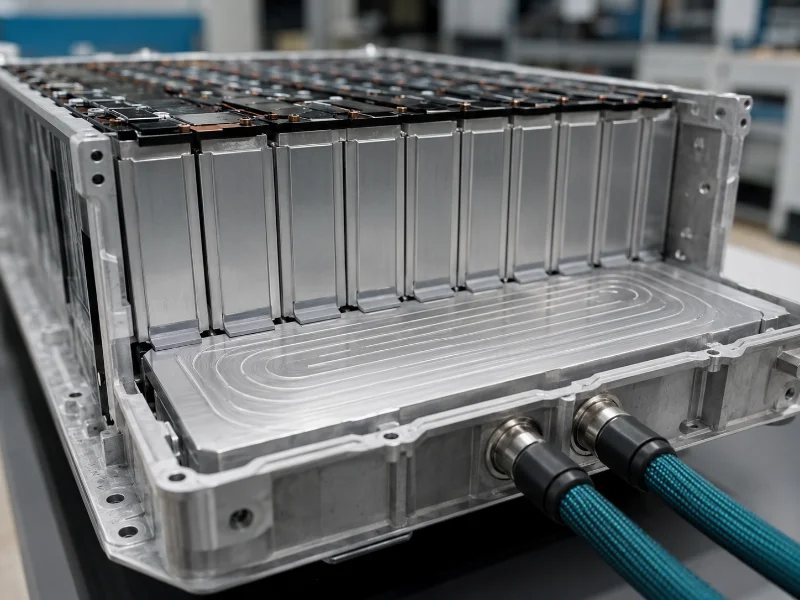
EV battery cooling keeps a lithium-ion pack inside a working temperature band while limiting how far individual cells drift from one another in temperature, and the method that achieves both depends on measured cell heat generation, the uniformity target the cells carry, and the packaging available. Air, indirect liquid cold plates, direct refrigerant, immersion, heat pipes and phase-change buffering each reach a different physical limit first. Heat generation has to come from cell-level data across the expected current, state of charge and temperature range. Pack capacity multiplied by C-rate describes electrical throughput, so it is not a substitute.
How EV Battery Cooling Works and What It Is Actually Controlling
An EV battery cooling system carries heat out of the pack while holding two separate targets: an absolute temperature band for the cells, and a ceiling on how far cells may drift from one another. Which target binds first depends on the flow path, the packaging and the cell-to-coolant interface.
Heat generation inside the pack has several contributors. Irreversible heat comes from ohmic and polarisation losses in the cells, and reversible entropic heat comes from the electrochemistry itself. Busbars, tabs and contact resistances add more, so joints often become hot spots before cell bodies do. All of these move with current, internal resistance, state of charge, temperature, ageing and charge direction. A cooling load worth designing to therefore comes from calorimetry, a supplier heat-generation map, or a validated electrothermal model run across your actual duty cycle.
Published guidance on the absolute band splits. An E-Mobility Engineering feature on EV battery cooling, an engineering trade title, puts best performance and longest life at roughly 20–25 °C. Saur Energy’s comparison of liquid and air cooling describes a workable operating region closer to 20–40 °C. The two figures answer different questions: the narrow one is a longevity optimum, the wide one an operating tolerance. A design that adopts the tolerance as its target will pass its own acceptance test and still age faster than the cell datasheet assumes. Both are industry generalisations, and the approved cell specification takes precedence over either.
One boundary is worth drawing early. Normal thermal management controls working temperature, spread, ageing and auxiliary energy use. Thermal runaway and propagation safety is a separate discipline: detection, venting, isolation, occupant warning and cell-to-cell propagation resistance. For road vehicles it is addressed by ISO 6469-1:2019/Amd 1:2022, which covers safety management of thermal propagation for rechargeable energy storage systems. A cooling loop sized for normal operation is not a propagation strategy, and no version of that standard prescribes a cooling method, a plate size or an optimum cell temperature.
Why Liquid Cooling Does Not Automatically Beat Air Cooling
Choosing between air and liquid cooling for an EV pack turns on surface heat flux, the flow actually available and the uniformity target, which leaves pack capacity and vehicle class poor predictors on their own. Air-cooling capability moves with air mass flow, allowable air temperature rise, inlet temperature, cell-to-air surface area, duct bypass and flow distribution, fan static pressure, ambient conditions and whether the air is conditioned first. Liquid capability moves with plate area, contact resistance, flow rate, inlet temperature, channel geometry, pressure drop and chiller capacity. Neither list collapses into a single wattage threshold. Published thresholds usually turn out to be one supplier’s product envelope.
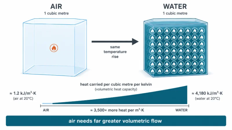
What can be stated is how differently the two scale. At about 25 °C, air carries roughly 1.005 kJ/kg·K at a density near 1.225 kg/m³, or about 1.2 kJ per cubic metre per kelvin. Water carries about 4.18 kJ/kg·K at roughly 1,000 kg/m³, or about 4,180 kJ per cubic metre per kelvin. For the same heat removed at the same fluid temperature rise, air therefore needs on the order of 3,000 times the volumetric flow. That gap sets the comparison. The figures assume sensible heat only, atmospheric pressure and pure water; a glycol mixture carries less. In practice an air-cooled design runs up against the duct volume and fan power the packaging allows, and it loses uniformity before it loses average temperature.
The two paths also combine. Phase-change material can buffer peaks inside an air-cooled enclosure, and a mostly air-cooled system can carry a small liquid loop serving only the highest-flux modules. Stationary storage sits under different packaging and service constraints, and it is a separate comparison.
Six Cooling Methods and the Limit Each One Reaches First
Six cooling approaches appear in current EV pack design, and which one reaches its limit first depends on surface heat flux, packaging volume and the fluid’s compatibility with live cells.
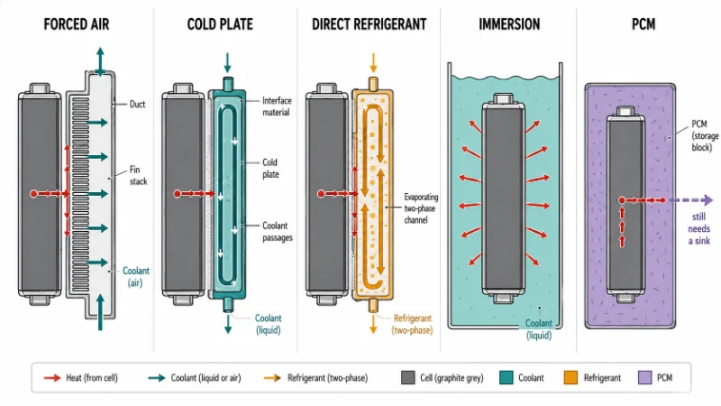
| Method | Heat path | More suitable when | Limit reached first |
|---|---|---|---|
| Forced or conditioned air | Cell surface to air to duct or enclosure | Heat flux is low, airflow is available, wider spread is tolerable | Low volumetric heat capacity and airflow maldistribution |
| Indirect liquid, cold plate | Cell to interface material to plate to coolant | Higher heat flux, or spread has to be tight | Interface resistance, pressure drop, leak management |
| Direct refrigerant | Cell or plate to evaporating refrigerant | Packaging favours tying the pack into the refrigerant circuit | Refrigerant distribution and superheat control across parallel branches |
| Immersion, direct dielectric | Cell outer surface to dielectric fluid | Surface heat flux is high or packaging is very compact | Fluid viscosity, pumping power, compatibility, serviceability |
| Heat pipe | Cell to phase change inside a sealed pipe, then to a sink | Heat has to move out of a confined spot to a cooler region | Capillary limit, orientation, and the sink still has to exist |
| PCM buffering | Cell to latent heat storage | Transient peaks need smoothing | Stored heat still needs a regeneration or rejection path |
Maturity varies across that list. Air cooling and indirect liquid cooling are established in production, and refrigerant-based approaches appear in production vehicles. Immersion cooling and large-scale PCM systems remain more common in pilot programmes and advanced development, with indirect liquid cooling the most established approach for high-energy passenger packs today. The same feature notes that silicone oils investigated as dielectric fluids are viscous enough to raise pump power noticeably, and that one tested fluid behaved non-Newtonically under pumping load.
Cell format shifts where these limits fall, because it changes the available contact area, the internal conduction path and the direction from which cooling works best. That comparison needs the actual cell dimensions and the surfaces available for thermal contact. Flow layout matters for the same reason. In a single-pass serpentine channel, cells near the outlet can run hotter because the coolant has already absorbed heat upstream, while parallel or multi-inlet layouts can reduce or redistribute that gradient.
Which Pack Variables Decide the Method, and Which to Establish First
Seven variables govern an EV battery cooling decision, and each one has a legitimate origin: a cell datasheet, a validation requirement, or the duty cycle the pack actually runs.
| Variable | Where the value comes from | What it constrains |
|---|---|---|
| Cell heat generation | Calorimetry, supplier heat-generation map, or validated electrothermal model | Every downstream sizing step |
| Cell-to-cell spread limit | Cell and pack validation requirements, stated with the measurement condition | Whether air remains an option at all |
| Coolant temperature rise | Flow rate, plate area, channel layout | One term of the spread budget |
| Interface resistance | Bond-line thickness, filler conductivity, surface flatness | Achievable cell temperature at a given plate temperature |
| Enclosure and airflow path | Ingress rating, service access, packaging volume | Feasibility of conditioned air |
| Working fluid | Electrical conductivity, low-temperature viscosity, material compatibility | Leak consequence and service regime |
| Charge derating and shutdown thresholds | Approved cell specification and BMS safety concept | Sustained fast-charge behaviour |
The seven converge together, though two of them are worth defining early. Cell heat generation comes first: plate area, channel count, flow rate and pump selection all take it as an input, so a change here propagates through every later decision. The spread limit comes next, and it is the less negotiable of the two. It originates with the cell, which leaves it largely outside the designer’s control. Enclosure type and working fluid can usually be revisited later in the design without redoing the sizing.
Stated against our own interest: where a pack’s measured dissipation is modest and the packaging allows conditioned air, a liquid loop adds pumps, fittings, coolant service and leak detection for margin the duty cycle may never call on. A spread budget on paper will show that faster than a supplier comparison will.
Coolant conductivity limits that changed in 2025
Two documents moved coolant selection recently, and older coolant specifications may not reflect either.
- GB 29743.2-2025, Motor vehicle coolant, Part 2: Electric vehicle coolant. In force in China from 1 October 2025, it caps the electrical conductivity of coolant as supplied at 100 µS/cm, with a permitted rise in service. Action: confirm compliance status with your coolant supplier before specifying a fluid for any platform sold into that market.
- ASTM D8566-24, Standard Specification for Glycol-Based Electric Vehicle Coolant with Low Electrical Conductivity. Approved 15 May 2024 under ASTM subcommittee D15.26, it reports a maximum electrical conductivity of 100 µS/cm for fresh coolant. Action: check whether your loop is specified to this document or to a legacy engine-coolant specification, since conventional engine coolants sit orders of magnitude higher.
Neither document sets an optimum cell temperature, a uniformity target or a cooling flow rate. They constrain the fluid, and the thermal design stays yours.
Interface Resistance Between the Cell and the Cold Plate
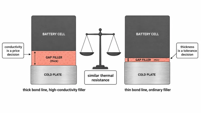
Interface resistance between a cell and its cold plate often governs achievable cell temperature more than the plate does, because the bond line is a series element whose resistance rises with thickness and falls with conductivity and area. The same feature makes the trade explicit. A 10 mm gap filled with a 10 W/m·K material carries about the same thermal resistance as a 1 mm gap filled with a 1 W/m·K material. That comparison holds all else being equal.
The thickness-and-conductivity relation carries a procurement consequence that rarely gets stated. Halving the bond line buys roughly what doubling filler conductivity buys. Thickness is a tolerance and flatness decision, while conductivity is a price decision. Thickness is often the cheaper lever. Specifying a premium thermal interface material to rescue a pack that runs hot is often the expensive route to a temperature drop a tighter stack-up would have delivered. The comparison assumes one-dimensional conduction and ignores contact resistance at the two surfaces, which grows when either surface is out of flat.
Coolant flow rate follows from the heat load and the rise you allow. From q = ṁ × Cp × ΔT, a load of 5 kW held to a 3 K coolant rise needs about 5,000 ÷ (3,300 × 3) ≈ 0.5 kg/s. The 3.3 kJ/kg·K figure comes from pure-component values for a 50/50 water–glycol mixture with ideal mixing assumed. Substitute your own measured load and your own fluid datasheet. What that calculation sizes is the coolant rise, one term in the cell-to-cell spread budget. The rest comes from manifold flow distribution, in-plane conduction across the plate, interface resistance, differences in per-cell heat generation, edge effects at the module boundary, and sensor placement and tolerance. We check what coolant rise a stated spread budget can absorb before comparing plate options.
When a plate is sized from total heat load alone and nobody writes the spread budget down, the pack often meets its average temperature target and still fails the uniformity check near the outlet. The correction then tends to arrive as more flow instead of a different manifold layout. In packs cycling daily in high ambient heat, the cells nearest the coolant outlet and the plate-to-cell bond line are usually the first places worth re-checking when measured spread starts to widen.
From Heat Generation Data to a Cooling Method Decision
An EV battery cooling decision rests on two inputs above all: a measured or modelled heat-generation profile, and a cell-to-cell spread limit stated with its measurement condition. Once both exist, method selection, plate sizing and flow rate follow with much less guesswork. Most of the disagreement about air against liquid turns out to be disagreement about those two numbers. Both are project-level and depend on your own duty cycle, so they are worth establishing on a sustained-rate test before you choose hardware.
If you already have a heat-generation profile and a stated uniformity target, the next step is a channel layout and interface stack checked against both, which is where our Battery Pack Thermal Management work starts. If you have neither, start with calorimetry or a supplier heat-generation map, because every sizing decision after that point inherits its accuracy.
FAQ
Does a parked EV still need battery cooling?
Sometimes. Buyer-facing coverage notes that some production EVs keep thermal management running while parked in high ambient heat, at a small energy cost, to limit ageing. Whether yours does is a model-specific behaviour worth checking in the owner documentation.
Can a pack be converted from air cooling to liquid cooling later?
Rarely without a pack redesign. Plate mounting, cell spacing, sealing and coolant routing are physical decisions fixed at pack layout, unlike control set points such as target coolant temperature, which stay adjustable afterwards. Treat the cooling method as settled once the enclosure geometry is frozen.
How often does coolant need replacing in a battery loop?
On the interval in the vehicle or battery-system service specification. Fluid-supplier data on inhibitor life and material compatibility should support that interval, and the loop’s metals, seals and conductivity drift all bear on it.
What has to change before immersion cooling suits a production pack?
Three things: a pumping-power budget that survives the fluid’s viscosity, seals and service access designed for a wetted pack, and volume supply of a qualified fluid. Heat transfer is rarely the blocker.
What does battery preconditioning do for charging speed?
Preconditioning brings the pack toward the window where the BMS will allow higher charge current, which is why one charger can deliver very different curves on a cold pack and a preconditioned one. Derating and shutdown thresholds come from the approved cell specification. Preconditioning also draws pack energy, so extra thermal capability costs range.
