

AI servers are cooled mostly by liquid today. Cold plates pressed onto the processors, rear-door heat exchangers on the rack, or full immersion in a non-conductive fluid have taken over because air alone can no longer carry away the heat of a dense AI rack. The heat follows a fixed path regardless of method. It leaves the silicon die, crosses a thin thermal interface layer, enters a metal cold plate or coolant, and finally leaves the building. Understanding that path, and where each cooling method taps into it, explains why the industry has moved from fans to fluids.
Why Air Cooling Runs Out at AI Rack Densities
Air cooling fails at AI densities because the heat per rack has outgrown what moving air can practically remove. A conventional enterprise rack draws on the order of 8 to 10 kW. AI training racks now reach 100 kW and beyond, and per-accelerator power has climbed from a few hundred watts to well over 1,000 W. NVIDIA’s Blackwell GPUs draw up to roughly 1,200 W each, according to IEEE Spectrum’s reporting. Pushing enough cold air across chips at that density means impractical fan power and noise long before the silicon is comfortable.
Airflow is the specific limit that gives out first. Air has a low heat capacity, so removing more heat means moving more air, and the volume needed climbs faster than the space and fan power available inside a dense rack. Past a certain point the fans consume a growing share of the power budget, hot spots form where airflow is uneven, and the processors begin to throttle to protect themselves. That is the wall AI hardware hit, and it is why the question shifted from how to cool AI servers with air to which liquid method to use.
The physics favor liquid by a wide margin. IEEE Spectrum notes that water can absorb on the order of 3,000 times as much heat per unit volume as air and conducts heat roughly twenty times better. That is why a liquid loop holds a chip’s junction temperature with a far smaller temperature difference than air ever could. Cooling is not a minor cost either. By some operator estimates it can account for up to about 40% of a data center’s electricity. That efficiency directly shapes operating cost, and with it how much compute a site can install in the same power envelope.
The Heat Path: From the GPU Die Through Thermal Interface Materials to the Cold Plate
Every cooling method starts at the same bottleneck: getting heat off the chip and across the tiny gap between the die or its lid and the cooling hardware. That gap is never perfectly flat, so a thin layer of thermal interface materials fills it and replaces insulating air with a conductive path into the cold plate or heat sink. When that interface is poor, no downstream loop, however cold, can pull heat out fast enough, and the processor throttles.
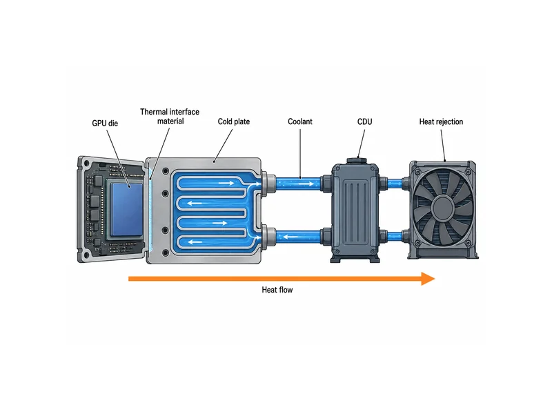
The interface matters because thermal resistances add up in series along the heat path. Heat has to cross the die-to-lid joint, the interface layer, and the cold plate wall before it ever reaches the coolant, and the weakest link sets the ceiling. A large, low-temperature cold plate cannot compensate for a poor interface directly under the chip. That is why the interface layer, though only a fraction of a millimeter thick, is treated as a design variable, not an afterthought.
Interface selection follows the assembly, not just the coolant. Larger or uneven gaps are usually bridged with conformable gap fillers or thermal gap pads chosen for how they handle mounting pressure and flatness, while thin, flat lids may use pastes or phase-change films. The specific conductivity and thickness follow from the material and mounting method, and no single part number fixes them. Component suppliers such as Trumonytechs work at this layer, matching cold plates and interface materials to the gap, assembly stress, and heat load of a given package. The same interface engineering governs battery-pack cooling.
Direct-to-Chip (Cold Plate) Liquid Cooling
Direct-to-chip cooling is the dominant approach for dense AI racks: a metal cold plate with internal channels sits directly on each processor and carries coolant a few millimeters from the heat source. Public descriptions of production systems put the share of rack heat captured this way at roughly 70 to 90%, while some air still handles residual heat from memory and power stages. The coolant is often water with glycol added to prevent freezing, corrosion, and biological growth, then routed through a coolant distribution unit (CDU) to outdoor heat rejection.
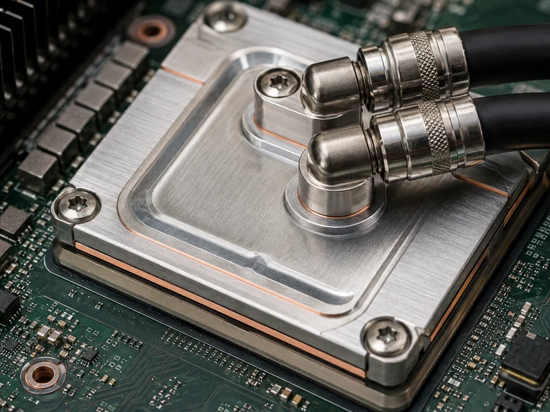
The CDU is the boundary that makes the approach practical at scale. It isolates the clean, controlled loop touching the chips from the facility water outside, and it distributes flow to each rack through manifolds. Operators can then run the chip-side loop at a temperature the servers want while the facility side rejects heat through dry coolers or chillers. Because the loop stays sealed, the same coolant recirculates instead of being consumed, and the design builds in leak detection and quick-disconnect fittings as standard equipment.
Single-Phase Direct-to-Chip
Single-phase direct-to-chip keeps the coolant liquid the whole way, trading higher flow for a simpler loop. The fluid enters the cold plate, warms, and leaves without boiling, which keeps the system straightforward but demands steady pumping. NVIDIA’s warm-water designs, for example, run a mix of about 75% water and 25% propylene glycol and accept coolant as warm as 45 °C in a closed loop. That warmth lets many sites reject heat with dry coolers instead of energy-hungry chillers.
Two-Phase Direct-to-Chip
Two-phase direct-to-chip lets the coolant boil on the hot surface, using the latent heat of evaporation to move far more heat per unit of flow. IEEE Spectrum describes two-phase methods offering on the order of ten to a hundred times the cooling capacity of a single-phase liquid, at a fraction of the flow rate. The trade-off is a more complex sealed system and fluids that must be selected and contained carefully.
Rear-Door Heat Exchangers and Hybrid Air-Liquid Cooling
Rear-door heat exchangers cool the air leaving a rack, not the chip itself, which makes them the easiest liquid step for an existing air-cooled room. A liquid-cooled coil replaces the rack’s back door, the servers’ own fans push hot exhaust through it, and chilled water carries the heat away before it reenters the room. Reported capacities run up to roughly 75 kW per rack, enough to extend air-cooled facilities into moderate AI density without plumbing liquid to every chip. Passive doors rely on the server fans, while active doors add their own fans for more headroom.
Hybrid designs pair direct-to-chip plates with air or rear-door cooling in the same rack. The cold plates take the concentrated load from GPUs and CPUs while air handles the lower-power components, which is often the practical path when a site cannot commit to full liquid at once.
Immersion Cooling
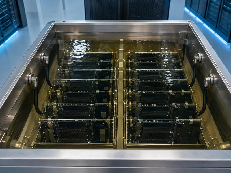
Immersion cooling submerges whole servers in a non-conductive dielectric fluid, removing the need for fans and per-chip plumbing. Because the fluid contacts every component, heat leaves the boards uniformly across every surface, not through a single plate, which supports very high density in a compact footprint. Removing the fans also removes a common failure point and much of the acoustic noise, and it frees the volume those fans and heat sinks would occupy. The trade-offs are different hardware, new maintenance procedures, and fluid handling. Servicing a board means lifting it from the tank, and operators even swap out some standard thermal interface materials because they can degrade in the fluid over time.
Single-Phase Immersion
Single-phase immersion keeps the dielectric fluid liquid and pumps it to an external heat exchanger. The approach is mechanically simple and eliminates fans, but it still needs circulation and periodic fluid testing to stay reliable.
Two-Phase Immersion
Two-phase immersion lets the fluid boil off the components and condense on a cooled coil above the tank, again exploiting latent heat for very high heat flux. Engineered dielectric fluids are formulated to boil at low temperatures, reported roughly in the 34 to 56 °C range, so components stay near a controlled temperature. Fluid cost and containment are the main constraints.
Matching a Cooling Method to Rack Density
The choice of method follows rack power density more than any other single factor. Air and rear-door cooling still serve lower-density racks. Direct-to-chip becomes the default once a rack passes the density where air alone throttles, commonly cited in the tens of kilowatts. Immersion is reserved for the highest, most space-constrained densities. The verifying question for any deployment is where the heat actually concentrates and whether the interface and cold-plate design can move it at the target junction temperature.
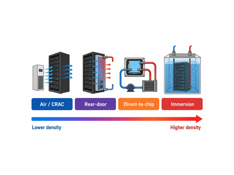
Density is not the only variable, though. Whether a site is retrofitting an air-cooled room or building new changes the answer. Rear-door and hybrid designs reuse existing racks and airflow, while full direct-to-chip and immersion assume plumbing, CDUs, and staff trained on liquid. Available facility water temperature matters too: a design that accepts warmer coolant can lean on dry coolers instead of chillers, which is where much of liquid cooling’s efficiency comes from. The consistent thread is that no method escapes the heat path. The interface material and cold-plate design under each chip must be verified against the real heat load before the surrounding loop is chosen.
| Method | How it taps the heat path | Typical fit | Main trade-off |
|---|---|---|---|
| Air / CRAC | Blows cold air over heat sinks | Lower-density racks | Runs out of headroom in the tens of kW |
| Rear-door heat exchanger | Cools rack exhaust air with a liquid coil | Moderate density, air-cooled retrofits | Still depends on server fans at the chip |
| Direct-to-chip cold plate | Liquid a few mm from the die via a cold plate | Most dense AI racks (100 kW+) | Needs cold plates, CDUs, and TIM at each chip |
| Immersion | Whole server submerged in dielectric fluid | Highest, space-constrained density | Different hardware, fluid handling, maintenance |
Conclusion
The short answer is that AI servers are cooled by moving heat into a liquid as close to the chip as the density demands: cold plates for most AI racks, rear-door exchangers to stretch air-cooled rooms, and immersion at the extreme. The judgment that matters is matching the method to rack power density and to the heat path. The most-missed point is that liquid cooling is not simply a swap of coolant. The interface between the die and the cold plate, its flatness, and its material set decide whether any loop can hold the processor in range. Follow the watts from the die outward, and the appropriate cooling method usually declares itself.
FAQ
Why can’t fans cool a modern AI GPU anymore?
Fans run out of headroom because a single AI accelerator can dissipate over 1,000 W and a rack can exceed 100 kW. That is far past what moving air removes at a practical fan power and noise level. Liquid carries far more heat per unit volume, so it holds the junction temperature with a much smaller temperature rise.
What sits between the GPU and the cold plate?
A thin thermal interface layer sits between the chip and the cold plate, filling the microscopic, uneven gap so heat conducts instead of stalling in trapped air. The material, whether a pad, gel, paste, or phase-change film, is chosen for the gap size, flatness, and mounting pressure of the package.
How is direct-to-chip cooling different from immersion cooling?
Direct-to-chip cools only the hottest components through a cold plate while air or another loop handles the rest, whereas immersion submerges the entire server in dielectric fluid. Direct-to-chip retrofits more easily into existing racks, and immersion reaches higher density but needs different hardware and fluid handling.
Does liquid cooling save water?
Liquid cooling can save water when it runs as a closed loop rejected through dry coolers, since the same coolant recirculates instead of evaporating. Whether a site actually saves water depends on its heat-rejection design and climate, not on the cold plate alone.
What rack density requires liquid cooling?
Liquid cooling generally becomes necessary once rack density climbs into the tens of kilowatts, where air can no longer prevent throttling. The exact crossover depends on the servers, airflow, and inlet air conditions, so it should be verified per deployment, never assumed.
Further Reading
- Next-Gen AI Needs Liquid Cooling (IEEE Spectrum) — IEEE Spectrum, the flagship publication of the IEEE professional engineering body. Supports the water-versus-air heat-capacity comparison and the single-phase versus two-phase capacity difference used above.
- Liquid Cooling Options: RDHx, Direct-to-Chip, Immersion (Data Center Knowledge) — Established data-center industry publication. Supports the comparison of rear-door, direct-to-chip, and immersion methods and their trade-offs.
Related Articles
- Potting Compounds — Covers how encapsulants protect and conduct heat away from electronic assemblies, useful when a cooling design also has to seal and mechanically support components.
- What is Thermal Gel Used For? — Explains where thermal gel fits among interface materials for filling uneven gaps, the same interface layer this article flags as decisive.
- What Thermal Paste Is for Computers — Breaks down how thermal paste works at CPU and GPU interfaces, the microscopic gap that sits between a die and its cold plate.
- When to Use Thermal Gel? — Helps decide when a gel beats a pad or paste for a given gap and mounting condition, extending the interface-selection logic here.
- Which Thermal Paste Is Best? — Clarifies how to judge a “best” paste by target outcome and constraints, useful once you know a poor interface throttles any liquid loop.
