
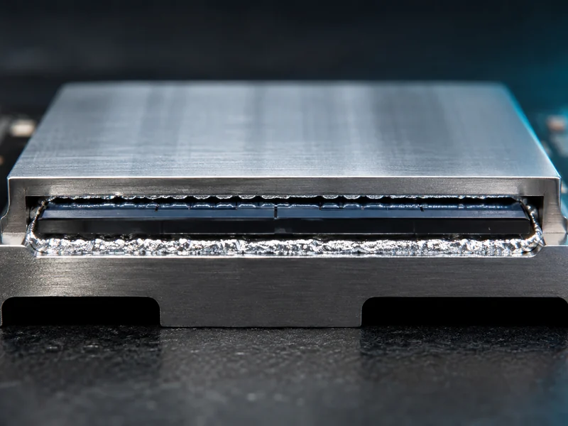
Solder thermal interface material carries heat across a joint by forming a solid metallurgical bond instead of a compliant polymer layer. That metal bond is why it can reach lower thermal resistance than a paste or pad when the joint is thin and fully wetted, and also why it stays confined to a narrow set of interfaces. Its main use is at the die level of high-power semiconductor packages, where a thin, flat, solderable gap sits between the silicon and a heat spreader. Its main limit appears as soon as the interface grows larger, less flat, or mechanically active, because a stiff metal layer does not tolerate the movement that bigger assemblies impose.
This article treats solder TIM as a die-level bonding material and compares it with the softer, compliant interface materials used higher up the heat path. It does not cover solder-paste metallurgy for electrical interconnects, reflow-profile engineering, or the electrical joints in a package; those are separate problems that share the word solder.
What Solder Thermal Interface Material Is
Solder thermal interface material is a fusible metal layer, reflowed between two mating surfaces to bond them into a single low-resistance heat path. It is often abbreviated sTIM or STIM, and it typically uses a tin-based or other low-melting-point solder alloy that melts, wets both surfaces, and cools into an intermetallic bond. That reflow step is what separates it from every polymer TIM: instead of pressing a soft material into place, the process forms a continuous metallic joint.
The canonical position for this material is between a processor die and its integrated heat spreader (IHS). Intel documents this layer as the solder thermal interface material that sits between the die and the IHS to raise conductivity across that joint. The same idea applies to high-power ball grid array (BGA) packages and to power-electronics dies, where the interface is small, planar, and can be given a solderable finish.
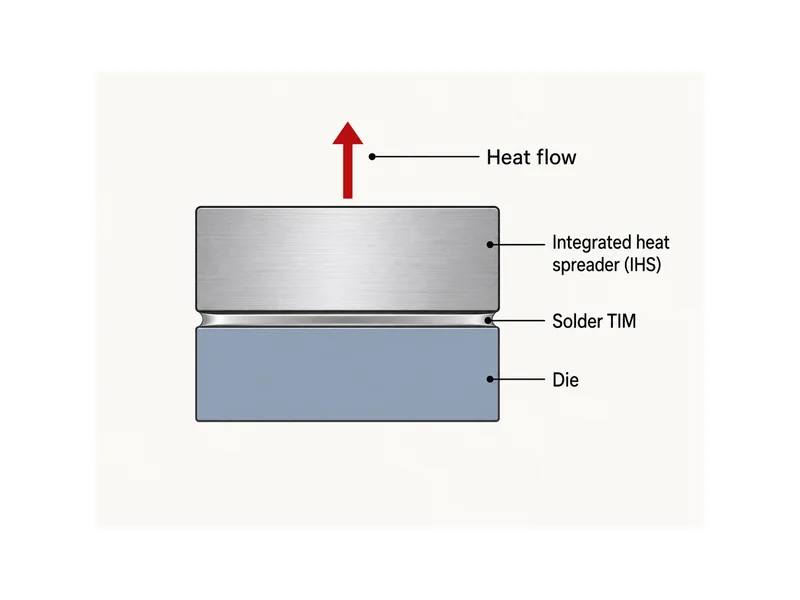
Solder TIM belongs to the broader class of metal interface materials, which also includes soft-metal foils, liquid metals, and sintered silver. What these share is a metallic conduction path; the heat moves through metal, not through a filled polymer. That path is both the source of the performance and the source of the constraints, and the trade between the two is the subject of most of this article.
Why Solder TIM Reaches Lower Thermal Resistance
Solder TIM reaches lower thermal resistance for two reasons: bulk metal conducts heat far better than a filled polymer, and a reflowed joint drives down the contact resistance that dominates a thin polymer bondline. Indium Corporation reports a bulk thermal conductivity around 86 W/m·K for its metal TIM. Polymer thermal greases generally fall in the 2 to 10 W/m·K range, and specialized formulations reach into the teens. Air, the gap the TIM is displacing, sits near 0.026 W/m·K, so every TIM is an improvement; the open question is how large that improvement is. A filled polymer carries heat through conductive particles suspended in a resin, and the resin and the particle-to-particle contacts cap how high the bulk value can go. A reflowed metal layer has no resin in the path, so conduction runs through continuous metal. That is the difference between the metal class and the polymer class, before contact resistance is even counted.
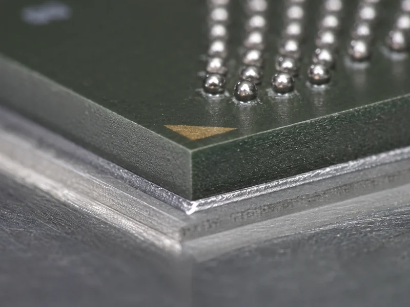
The contact itself is the second advantage. A reflowed metal joint wets both mating faces and forms intermetallic contact, so the interfacial resistance that dominates a thin polymer bondline is much lower. In a thin, well-wetted, and verified joint, that contact resistance can fall below what a polymer interface reaches. That is why solder is the reference point engineers use for the lowest-resistance tier of interface. The exact value depends on the alloy, the bondline, the wetting quality, and the test conditions, so it is read as a low interfacial resistance, not a fixed number that transfers to every solder joint.
A metal joint also removes two failure modes that affect greases and some pastes. Pump-out is where a fluid TIM is slowly squeezed out of the interface under thermal cycling; bake-out is where volatiles drive off and leave voids behind. Both depend on the material staying fluid or semi-fluid. A solidified metal bond does not migrate that way, so it is not subject to pump-out or bake-out in the interface the way a grease or a soft paste can be.
The Reliability and Process Costs Behind That Performance
Higher conductivity does not make solder TIM the default choice, because the same rigid bond that lowers resistance also concentrates stress. A solder layer is stiff and has low compliance. When the die and the spreader expand at different rates, the mismatch in coefficient of thermal expansion (CTE) loads the joint directly, with no soft layer to absorb it. Over repeated thermal cycles that stress drives fatigue and cracking in the TIM layer. That fatigue is the reliability limit solder TIM alloys are engineered around.
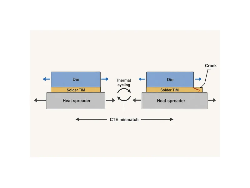
Bondline thickness sits in the middle of that trade. A thicker metal bondline adds thermal resistance and works against the low resistance the joint was chosen to deliver, so the layer is kept as thin as the interface allows. Because that same stiff layer also has to carry the CTE strain, the bondline is one of the variables a joint design has to balance, not simply minimize. A change made for one reason gets weighed against its effect on the other.
Coplanarity carries weight for the same reason. A metal joint has little ability to conform to a warped or uneven surface, so flatness and surface preparation matter more here than they do with a soft pad, which can take up some of that variation on its own. On a die-to-spreader joint the mating faces are small and can be held flat; as the interface grows, holding that flatness gets harder, and the metal bond has less tolerance for what remains.
Process narrows the window further. Solder must wet the surfaces it bonds, which usually means both faces need a compatible, solderable metallization; a bare, plastic, painted, or anodized surface will not wet. The interface also has to survive a reflow step, so anything nearby that cannot take that temperature excursion has to be accounted for in the assembly. These are not reasons to avoid solder TIM; they are the conditions that decide whether an interface can accept it at all.
Matching the Interface Material to Gap, Stress, and Surface
The material class should follow the interface, not the reverse, so the practical decision starts with gap size, assembly stress, surface, and whether a reflow step is even possible. Solder TIM fits where the gap is thin and planar, the mating faces are solderable, and the assembly can go through reflow. In that setting the priority is the lowest interface resistance a thin, well-wetted metal joint can deliver in a small, high-flux area such as a die-to-spreader joint. Move away from any one of those conditions and the case for a metal bond weakens quickly. Matching material to interface this way is the core of thermal interface material selection once the heat path leaves the die.
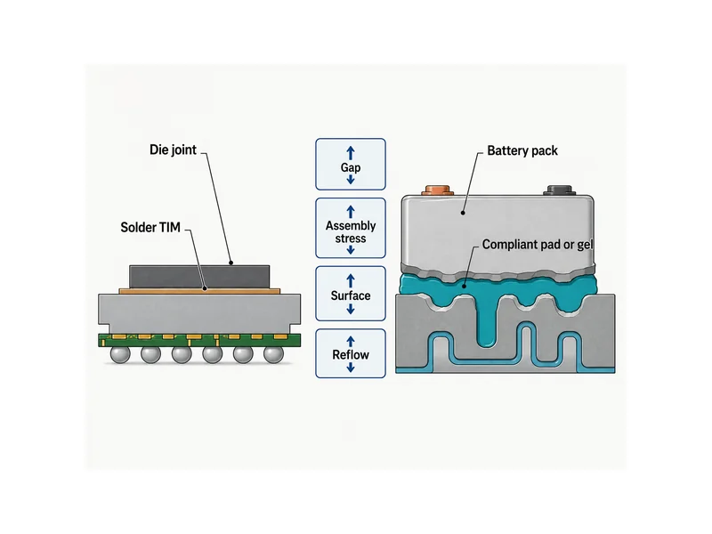
At module and pack level the interface is larger and less uniform. Gaps are bigger and vary across the assembly, and the surfaces are painted, anodized, or plastic, none of them solderable. The cells move as they charge and age, and the assembly is built by dispensing or manual placement, not by a reflow step. Those conditions favor compliant materials: soft thermal pads and dispensable gels that conform to uneven interfaces under low assembly stress, plus structural adhesives where the interface also has to carry load. A stiff solder joint in that environment would fight the very movement and tolerance the assembly needs to accommodate.
The battery-pack interface stack diverges from the die-level solder case here. At pack scale the design problem is not chasing die-level conductivity; it is conforming to real, uneven gaps and absorbing cell movement. That points to compliant and load-bearing classes: thermal pads and gels for the low-stress cell-to-cold-plate heat path, and a structural adhesive where the joint has to be both thermal and load-bearing. These are the interface classes Trumonytechs works in at pack level, and none of them is a metal solder TIM — the selection follows the interface conditions, not a conductivity ranking.
Conclusion
The useful way to place solder thermal interface material is to define the interface regime before reaching for the highest-conductivity option. Solder TIM is the right answer for a thin, flat, solderable, reflow-capable joint in a high-flux die package, where its metallic bond and low interfacial resistance are worth the CTE and process constraints. It is the wrong answer for the larger, uneven, mechanically active interfaces at module and pack level, where compliance, conformability, and load-bearing bonding decide reliability. Read the gap, the assembly stress, the surface, and the process first; the conductivity number becomes decisive only once those conditions confirm a metal joint can actually be used and survive.
FAQ
Is solder TIM better than thermal paste for a high-power die?
For a thin, flat, solderable die joint that goes through reflow, solder TIM reaches lower thermal resistance than paste and avoids pump-out. On that interface it outperforms paste on conductivity and contact resistance. Whether it is the better choice still depends on whether the interface can accept a reflowed metal bond. On an interface that is uneven, non-solderable, or mechanically active, a paste or a compliant TIM is the more reliable choice even though its conductivity is lower.
Does solder TIM need a solderable surface?
Solder TIM generally needs both mating faces to be solderable, because the material has to wet and bond metallurgically to form its low-resistance joint. Bare plastic, painted, or anodized surfaces usually cannot be wetted, so they need a compatible metallization first, or a different TIM class. This surface requirement is one of the main reasons solder TIM stays at the die and package level and does not move out to larger assemblies.
Why does a solder TIM crack under thermal cycling?
A solder TIM cracks under thermal cycling because it is stiff and cannot absorb the CTE mismatch between the parts it bonds. As the two surfaces expand and contract at different rates, the strain concentrates in the rigid metal layer, and repeated cycles drive fatigue and cracking. Managing it is a joint-design problem — the alloy, the bondline, and how well the CTE of the bonded parts is matched all feed into it — and any change made to ease the strain is weighed against the thermal resistance it can add.
Can solder TIM be used in an EV battery pack?
Solder TIM does not fit the typical cell-to-cold-plate interface of an EV battery pack. Those gaps are usually large and uneven, the surfaces are usually not solderable, and the cells move as they cycle, so the thin, flat, solderable, reflow-capable conditions solder TIM needs are generally absent at that interface. Packs instead use compliant thermal pads and gels for the conforming heat path, and a structural adhesive where the joint must also carry load.
Further Reading
- Thermal interface materials for high-power BGAs — industry technical article on the high-flux BGA interfaces where metal and phase-change TIMs are weighed against grease, supporting this article’s point about where the lowest-resistance interfaces matter.
- Thermal interface material selection guide — independent technical guide comparing TIM classes by conductivity, bondline, and mechanical trade-off, useful background for the gap-and-stress selection logic above.
Related Articles
- What is Thermal Gel Used For? — Covers where a conformable thermal gel belongs in a heat path and how it fills gaps that rigid pads and pastes cannot.
- What Is Thermal Paste Made Of? — Breaks down the filler-in-carrier makeup of thermal paste, a useful contrast to the solder metal bond discussed here.
- Potting Compounds-Complete Material Selection Guide — Explains how potting compounds protect and cool electronics, a different interface-material job from a die-level solder joint.
- New Advances in Thermal Interface Materials Enhance Electronics Cooling Efficiency — Surveys newer thermal interface materials and how they close contact gaps to cut air out of the heat path.
- Phase Change Thermal Pad — Shows how a phase-change pad softens across a transition band under clamp pressure, a compliant alternative to a rigid solder joint.