
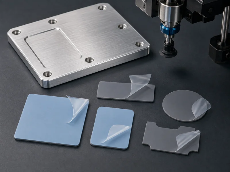
A die cut thermal interface material is a thermal pad, film, or conductive layer that is cut to its finished shape before it reaches the assembly line, instead of being dispensed as a liquid or spread as a grease. For a battery-pack or power-electronics engineer, that pre-formed shape is the point. It drops into place with repeatable thickness and area, it can be picked and placed by automation, and it carries its own release liner. This article covers the main types of die-cut thermal interface materials, how to choose between a pre-cut pad and a dispensed gap filler, and the variables that decide which material fits your interface. It does not cover dispensing equipment, cure ovens, or the electrical design of the pack; it stays with the interface layer itself.
What “die cut” changes about a thermal interface material
Die cutting changes how consistent and how automatable the interface is; it does not change what the material is made of underneath. A pre-formed part arrives with a repeatable footprint and a repeatable nominal thickness, held within a stated manufacturing tolerance, which is what lets you predict compression and interface resistance across many assemblies. The same broad thermal-interface need can be met by a pre-formed part or by a dispensed system, but the exact formulation and process have to be confirmed against a specific grade. Do not assume them from the format. Greases and two-part epoxies do not support die cutting at all, so choosing a die-cut format is partly a choice about process repeatability, and only partly about raw thermal numbers.
The trade-off you accept with a pre-cut part is that thickness is fixed at the value you order, so the pad has to be soft enough to conform to the real gap in front of it. A die-cut pad that is too firm bridges high spots and leaves voids over the low areas. To catch this, measure the compression force the pad exerts at your actual gap and weigh it against the cell and joint loads it feeds into; the rated conductivity alone will not tell you. Conformability under the compression your stack allows is the one variable that drives most of the type and hardness decisions further down.
The main types of die-cut thermal interface materials
Most die-cut thermal interface materials fall into a few families, and each trades conductivity, insulation, and softness differently. The families below survive as stamped, liner-backed parts; a purely liquid material such as grease or a two-part filler is a different format, compared separately in the next section.
Gap pads and thermal pads
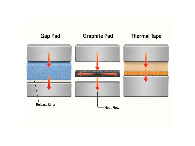
Gap pads and thermal pads are the workhorse die-cut format: soft, filled silicone sheets cut to shape and backed with a liner. Softer, thicker gap-pad grades close larger or less flat gaps and keep compression force low on fragile parts. Firmer thermal-pad grades, sometimes reinforced with fiberglass for tear resistance, suit thinner, flatter interfaces. Their conductivity comes from ceramic fillers such as aluminum oxide or boron nitride, and raising the filler loading tends to raise conductivity while also raising hardness. A very high number on the datasheet can therefore mean a stiffer pad that conforms worse. If you are sizing a pad mainly on its rated value, treat gap pad thermal conductivity as one input to weigh against softness, not a figure to maximize on its own.
Graphite pads and films
Graphite pads and films are worth considering when you need high in-plane heat spreading and can accept an electrically conductive layer. Graphite conducts heat strongly along its plane, and some grades tolerate high temperatures, which makes it useful for moving heat sideways to a sink. It is not an electrical insulator. Where the interface must also prevent a short between live parts, graphite either needs a separate dielectric layer or has to be ruled out, and that insulation requirement, not the in-plane conductivity, is usually the deciding constraint. Check continuous and peak temperature, in-plane versus through-plane performance, and the dielectric limit against the specific graphite grade, instead of assuming one figure covers the interface.
Thermal tapes and adhesive films
Thermal tapes and adhesive films earn their place when the interface also has to bond, not only conduct. A die-cut thermal tape carries a pressure-sensitive adhesive, so a part can be located and held with a peel-and-stick step, trading some thermal performance for mechanical attachment and simpler assembly. The adhesive can add a thin, less conductive layer, so tapes tend to suit lower-heat-flux joints, or cases where mechanical hold and speed matter more than the last fraction of a degree.
Die-cut thermal pad or dispensed gap filler: choosing by gap and assembly stress
The choice between a pre-cut pad and a dispensed gap filler turns on how uniform your gap is and how much stress the stack can take. Headline conductivity is not the deciding factor. A die-cut pad suits a consistent gap and reasonably flat surfaces, because the part is already sized and placed dry. A dispensed gap filler is a thermally conductive, usually two-part material that is metered onto the surface and cures in place. It conforms to uneven gaps and complex features, and whether it reaches a lower interface resistance than a given pad depends on the grade, the gap distribution, and the dispensing and cure parameters.
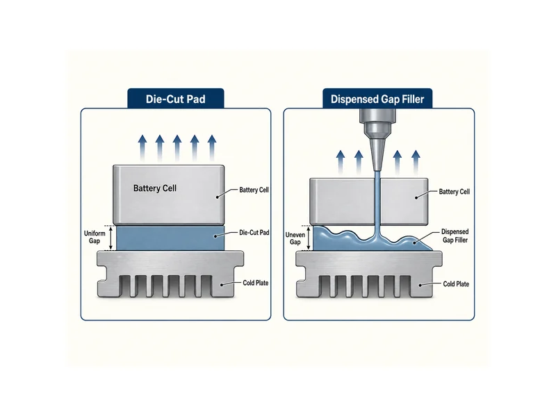
Assembly stress often settles the decision. A firm pad forced into a tight or uneven gap pushes reaction force into cells, boards, or solder joints, and that load can show up as cracked joints under vibration and thermal cycling. A liquid filler that conforms before it cures spreads contact and can apply less peak force, depending on how it is metered and cured. Against that, a dry pad needs no dispensing or cure step, which keeps handling and inventory straightforward. To choose between them, compare the force a candidate pad exerts at your worst-case gap with the load your most fragile component can survive, and fall back to a dispensed filler when that margin is thin.
Selecting a die-cut TIM: conductivity, insulation, temperature, and tolerance
Selecting a die-cut thermal interface material means ranking a short set of variables against your interface, because no single grade is best on all of them at once. In rough order of how often they decide the part:
- Gap and flatness: pick a thickness and softness that closes the real gap without over-compressing the parts around it.
- Electrical insulation: decide up front whether the layer must also be a dielectric barrier, which rules graphite in or out.
- Thermal conductivity: match it to your heat flux, remembering that higher-conductivity filled silicones are usually firmer. Published values vary with the material family, grade, thickness, and test conditions, so read them from the specific datasheet and confirm the test pressure and method before you compare.
- Operating temperature and durability: confirm the grade holds up across your full thermal-cycling range, not only at room temperature.
- Dimensional tolerance: hold the part tolerance the assembly and automation actually need, which is discussed below.
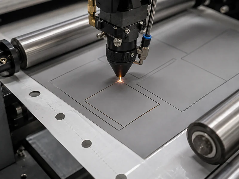
Achievable tolerance depends on the material, thickness, geometry, cutting process, and converter, so treat it as something to confirm for your specific drawing. As a general pattern, laser die cutting can hold a tighter dimensional tolerance than a steel-rule die, which matters when a pad has to register to a small footprint under pick-and-place; a looser tolerance burns more margin on placement. Confirm the manufacturable tolerance with your converter against the specific material and geometry.
One more discipline protects any conductivity number you compare. ASTM D5470, the standard test method for the through-plane thermal transmission properties of these materials, is what makes two datasheet values comparable in the first place, but a shared method is only the necessary condition. You still have to check that the thickness, test pressure, and other reported conditions match, because numbers from different methods or different pressures are not directly interchangeable.
Die-cut thermal interface materials in EV and ESS battery packs
In EV and stationary energy-storage packs, a die-cut thermal interface material often has to do two jobs at once: carry cell heat toward the cold plate and electrically isolate the cells from surrounding metal. One construction that meets both is a multi-layer die-cut pad — a thermal gap layer bonded to a thin polyimide dielectric film — so the same part conducts heat downward while the polyimide prevents metal-to-metal contact that could short a cell. The dielectric layer is thin but tough, which also helps it resist cut-through from burrs during assembly.
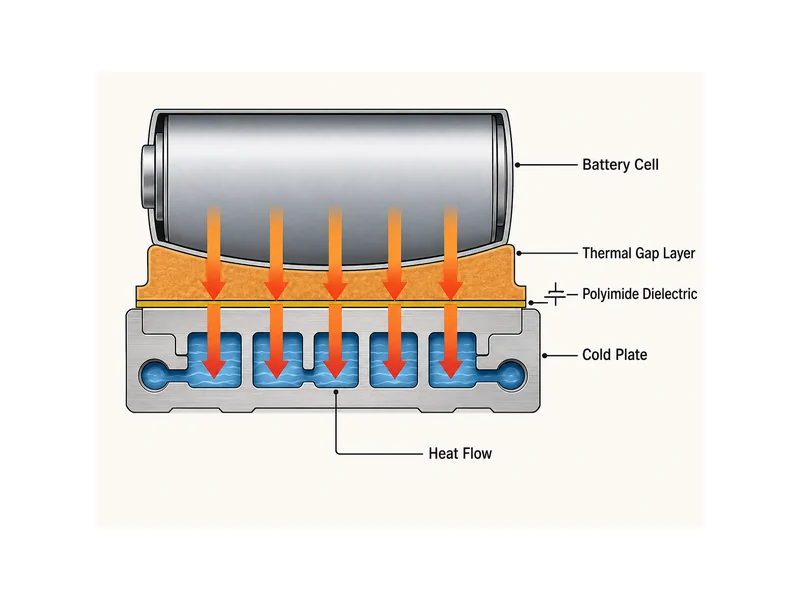
The pad has to be designed together with the rest of the heat path, not chosen in isolation. It performs only as well as the contact it makes with the cold plate below it, so match its thickness, softness, and flatness to the plate and the cell stack as one system; a datasheet figure alone will not settle those. Because a battery interface has to balance conduction, insulation, assembly stress, and cure-free handling in the same layer, it is worth treating the pad as one component of a matched set of industrial thermal interface solutions and liquid cold plates that share the same cell-to-coolant thermal path. Taking that system view, more than trusting any single conductivity figure, determines whether the interface holds up once the pack is built and cycling.
Conclusion
Choosing a die cut thermal interface material is mostly a sequence, not a search for the highest number. First fix the gap, the flatness, and whether the layer must also insulate. Then pick a type and hardness that conforms without over-stressing the parts. Only then compare conductivity, using figures measured the same way. The point most often misread is that a high rated conductivity does not guarantee a low real interface resistance, because a stiffer, higher-filled pad can leave voids that a softer, lower-rated pad would have closed. Before releasing a design, the checks worth doing are the compression force at your worst-case gap, the insulation requirement across the full stack, and whether a dispensed filler would conform better where the gap is uneven.
FAQ
Do I need a die-cut gap pad or a dispensed gap filler between my cells and cold plate?
Use a die-cut gap pad when the gap is consistent and the surfaces are reasonably flat. Use a dispensed gap filler when the gap is uneven, or when the assembly cannot tolerate the reaction force of a firm pad. The pad is dry, cure-free, and easy to automate. The liquid filler conforms to complex gaps and can reach a lower interface resistance in some cases, but it needs dispensing and cure steps. The deciding check is whether a candidate pad’s compression force at your worst-case gap stays under what your cells and joints can survive.
Can a die-cut thermal pad also act as a dielectric barrier to prevent short circuits?
Yes, when it is built with an insulating layer such as a polyimide film bonded into the pad. A multi-layer die-cut construction can conduct heat toward the cold plate while the dielectric layer prevents metal-to-metal contact between cells and surrounding structure. A plain graphite pad cannot do this, because graphite is electrically conductive and would need a separate insulator.
What thermal conductivity do I actually need for a cell-to-coolant interface?
Match the conductivity to your heat flux and gap, not to the highest available number, because a firmer high-conductivity pad can conform worse and raise the real interface resistance. Published values vary widely with the material family, grade, and thickness, so read them from the specific datasheet. Confirm any comparison uses values measured by the same method, such as ASTM D5470, and check that the thickness and test pressure match, because a shared method alone does not make two numbers interchangeable.
How tight a tolerance can I hold on a die-cut thermal pad for automated pick-and-place?
Laser die cutting can hold a tighter dimensional tolerance than a steel-rule die, which is what lets a small pad register reliably under automation. The tolerance to specify is the one the placement and the footprint actually require. Achievable tolerance depends on the material, thickness, and geometry, so confirm it with your converter against the specific part instead of assuming a fixed figure.
Further Reading
- TIMs: Four Types of Die Cut Products — manufacturer technical reference. Supports the type-by-type breakdown of die-cut interface products (graphite, thermal pads and films, thermal tapes, and gap fillers); treat vendor-specific figures as examples to verify.
- Gap filler vs gap pad — materials-supplier technical reference. Supports the pre-cut pad versus dispensed gap filler comparison, including application method, automation, and where each format fits.
Related Articles
- Advances in Silicone-Free Thermal Interface Materials — Explains when silicone-free interface materials are worth it, such as where outgassing or siloxane contamination rules out a standard filled-silicone pad.
- Are Thermal Pads Conductive? — Answers whether a thermal pad is electrically conductive or insulating, the same dielectric question that decides graphite in a battery pack.
- Conductive vs Non-Conductive Thermal Paste: A Selection Guide — Separates thermal from electrical conductivity when picking a paste, a useful contrast to the die-cut insulation trade-off here.
- Guide To Thermal Interface Materials — A broader primer on TIM types and selection factors for readers who want the full interface-material picture beyond die-cut formats.
- How Often To Replace Thermal Paste? — Explains why dispensed paste degrades and needs replacement, one reason a cure-free die-cut pad can simplify long-term maintenance.