
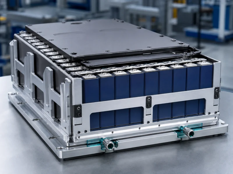
An energy storage battery module is the middle integration layer between a bare cell and a finished battery pack. At this layer, a fixed set of cells is wired in series and parallel and, for the first time, given mechanical support, basic monitoring, and a defined surface for heat removal. That heat-removal surface is why the module matters to a thermal engineer as much as to an electrical one. The path from a hot cell out to the coolant is largely set at the module level, before the pack is ever closed up. This article works through what a module is, what sits inside it, how cell format changes its thermal path, and what actually changes when modules are stacked into a pack.
What Is an Energy Storage Battery Module?
A battery module groups multiple cells into a single serviceable unit that raises voltage and capacity while adding the first layer of structural and thermal protection around the cells. Cells are the smallest electrochemical unit and set chemistry, nominal voltage, and cycle life. The module combines them so a larger system can be built and maintained in blocks instead of cell by cell. A pack, one level up, integrates several modules with a pack-level battery management system, thermal management, and an enclosure into the finished product that a vehicle or storage cabinet actually uses.
Voltage and capacity at the module level come directly from how the cells are connected. Series connections add voltage while parallel connections add capacity, so a module’s nameplate is a design choice, not a fixed number. Cell chemistry sets the starting point: lithium iron phosphate (LFP) cells sit at roughly 3.2 V nominal, while nickel-based chemistries such as NMC and NCA sit closer to 3.6–3.7 V. The exact figures should be read from the specific cell datasheet rather than inferred from the format.
Modules exist because scale and serviceability both improve when cells are handled in groups. A module that fails, ages, or needs replacement can be pulled and swapped without disturbing the whole system. Grouping also lets a manufacturer standardize a building block across products. A module built for one system rarely drops cleanly into another, which is one reason custom battery modules are engineered around a specific cell, pack geometry, and cooling interface, not sold as a generic part.
What’s Inside a Battery Module
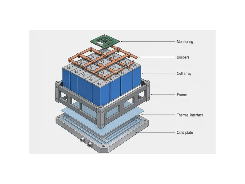
Inside a battery module sits a defined cell array plus the parts that connect, hold, monitor, and cool it — not just the cells themselves. Each element earns its place because a module has to survive vibration, thermal cycling, and years of charge and discharge without loosening or overheating. The core parts are consistent across most designs:
- Cell array: the cells arranged and fixed in a chosen series/parallel pattern that sets module voltage and capacity.
- Busbars and interconnects: the conductive links that carry current between cells and out to the module terminals.
- Mechanical housing or frame: the structure that holds cells in position, carries clamping load, and gives the module its handling stiffness.
- Monitoring electronics: cell-level voltage and temperature sensing, often a module monitoring unit that reports up to the pack-level BMS.
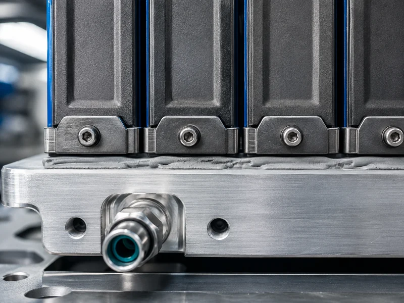
- Thermal interface and cooling surface: the gap-filling material and contact face that move heat from cells into a cold plate or cooling structure.
The last two items are where a module stops being a loose bundle of cells and becomes a managed unit. Monitoring at the module level catches an out-of-range cell early, and the thermal interface decides how effectively heat actually reaches the cooling path. Both are easy to underspecify and expensive to fix once a module is bonded and sealed.
How Cell Format Shapes the Module’s Thermal Path
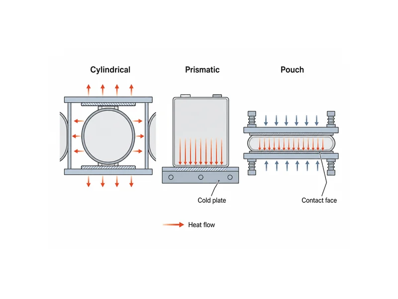
Cell format decides where heat leaves the cell and therefore what the module’s cooling surface has to look like. Cylindrical, prismatic, and pouch cells each present a different contact geometry, so a cooling approach that suits one format is rarely optimal for another. The three formats differ in both shape and how much flat surface they offer for heat transfer:
- Cylindrical cells (such as 18650 at 18 mm diameter and 65 mm length, 21700, or the larger 4680) have curved surfaces and concentrated terminals, so heat is often pulled from the ends or through the gaps between cells.
- Prismatic cells offer large flat faces and are well suited to a broad, even contact with a cold plate along one side.
- Pouch cells are thin and flexible, with large faces but low stiffness, so they need even support and controlled pressure to keep contact consistent.
Contact quality, beyond raw contact area, drives the result. Real cell faces are never perfectly flat, and stack-up tolerances leave a small, variable gap between the cell and the cooling surface. A thermal interface material fills that gap so heat is not throttled by trapped air. Assembly stress matters here too, because too little clamping pressure leaves voids while too much can distort a pouch cell or crack a rigid one. For a deeper split by format, our overview of EV battery module types walks through how each geometry trades energy density against ease of cooling.
Thermal Management at the Module Level
Module-level thermal management exists to keep every cell inside a narrow, uniform temperature band. Temperature spread across a module ages cells unevenly and, in the worst case, feeds thermal runaway. If one lithium-ion cell overheats or shorts, it can enter thermal runaway and propagate to its neighbors, and that failure mode is difficult to arrest once it starts. Keeping cells cool and, just as importantly, keeping them at similar temperatures is the module’s job before the pack-level system ever acts.
Cooling approaches fall into a few families, each with a different fit. Air cooling is simple and low-cost but struggles with temperature uniformity as energy density climbs. Liquid cooling through a cold plate moves far more heat and holds tighter uniformity, which is why it dominates higher-density modules. Immersion cooling submerges cells directly and is used where fire tolerance and heat load are both high. The right choice follows the module’s heat load, its temperature-uniformity target, and the allowable pressure drop in the coolant loop. No single method wins by default.
Temperature uniformity is a design target in its own right, separate from peak temperature. A module can hold an acceptable maximum cell temperature and still age unevenly if one corner runs consistently warmer than the rest. Each cell degrades along its own local temperature history. That is why a cooling layout judged only on the single hottest-cell reading can still fall short: the constraint is the spread across the array, and not one cell’s number.
The full path is worth reading as a chain: heat moves from the cell, through a thermal interface material, into a cold plate, and out with the coolant. Each interface in that chain adds resistance, so a strong cold plate paired with a poor interface still runs hot. Matching the interface material and the cold plate to the same cell format and duty cycle is where module cooling is won or lost. That match is the core of what our ESS cooling solutions are built to address. On the safety side, module construction is commonly evaluated to UL 1973, with propagation of a single-cell failure across a system assessed under UL 9540A. Both are useful reference points when a buyer needs to compare how seriously a module treats thermal-runaway containment.
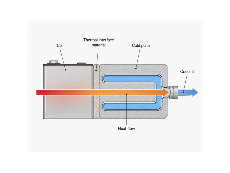
A common failure lives inside that same chain: a mismatch between the cold plate and the interface. A cold plate can be sized correctly for the module’s heat load, and the module can still develop hot spots when the interface material is chosen for the wrong cell format. That mismatch shows up as an interface too thin to fill a wavy pouch face, or too firm to keep even pressure against a rigid prismatic can. The answer there is not a stronger cold plate but an interface specified for the actual gap, flatness, and clamping conditions of that cell.
Module vs Pack: What Changes at the Next Level
Moving from module to pack trades some energy density for system-level control, protection, and packaging. Each level of assembly adds hardware — enclosures, a pack-level BMS, cooling manifolds, and structural protection — that carries mass and volume without storing energy. That overhead is why usable energy density typically steps down from cell to module to pack. The exact drop depends on chemistry and packaging and should be treated as a trend rather than a fixed percentage.
Responsibility also shifts as the boundary moves outward. A module handles local sensing and the first cooling interface. The pack-level BMS coordinates state of charge, balancing, and safety cutoffs across all modules, while the pack enclosure carries ingress protection and crash or environmental loads. Safety evaluation follows the same nesting, from cell-level UL 1642 up through module-level UL 1973 to system-level UL 9540A. That boundary, where module-level sensing ends and pack-level coordination begins, is the difference between battery module and battery pack.
Conclusion
The most useful thing to carry away is that a battery module is the level where thermal management first has to be designed in, not the pack. A module sets its own voltage and capacity through series and parallel wiring. It also fixes the cooling surface, the interface gap, and the clamping pressure that decide how well heat ever leaves the cells. The single most common misread is treating cooling as a pack-level afterthought when the cell-to-coolant path is largely locked at module assembly. Cell format is the first lever: it dictates whether a flat cold plate, an end-cooled arrangement, or a pressure-controlled pouch stack makes sense, and the thermal interface has to be chosen to match. Where those choices meet a real duty cycle, matched cold plates and interface materials are what turn a stack of cells into a module that holds its temperature band over its service life.
FAQ
Where does a module sit between a battery cell and a pack?
A module sits in the middle: a cell is the smallest energy-storing unit, a module groups cells with structure and basic monitoring, and a pack integrates modules with a full BMS, thermal system, and enclosure. Each step up adds voltage or capacity and more protection, while usable energy density steps down because enclosures, wiring, and cooling hardware add mass without storing energy.
What is inside a battery module?
A battery module contains a fixed cell array, busbars and interconnects, a mechanical frame, cell-level monitoring, and a thermal interface to a cooling surface. The monitoring and thermal interface are what turn a group of cells into a managed unit, and both are hard to change once the module is bonded and sealed.
How are cells arranged into a module for a BESS?
Cells are arranged in a fixed series and parallel pattern that sets the module’s voltage and capacity, then held in that pattern by a frame or housing so the geometry stays stable under vibration and thermal cycling. Series connections raise voltage and parallel connections raise capacity, so the arrangement is chosen for the target nameplate and for how heat has to reach the cooling surface.
Why does a battery module need a cold plate or thermal interface material?
A module needs a cold plate and interface material because heat has to leave the cells along a continuous path, and any trapped air or poor contact throttles that path. The interface material fills the small, uneven gap between cell and cold plate so heat is not blocked, and the cold plate then carries it away in the coolant; a strong plate with a poor interface still runs hot.
Does cell format change how a module is cooled?
Cell format changes both where heat exits the cell and how much flat area is available for a cooling surface. Prismatic cells suit broad side contact with a cold plate, pouch cells need even pressure to keep contact consistent, and cylindrical cells are often cooled from the ends or through inter-cell gaps.
Further Reading
- UL 9540A test method for thermal runaway propagation — UL Solutions (T1, standards body). Defines how single-cell failure propagation is actually tested and supports the module- and system-level safety references above.
- NFPA 855: Standard for the Installation of Stationary Energy Storage Systems — National Fire Protection Association (T1/T2, fire-safety standards body). Sets installation and fire-safety requirements for stationary energy storage and frames where module- and system-level thermal-runaway controls fit.
Related Articles
- What Is PV Battery Storage? — Explains how pairing solar panels with a rechargeable battery stores daytime electricity for evening use, and which specifications matter.
- Energy Storage Battery Packs in EV Charging Stations — Covers how buffer battery storage supports fast EV charging as charging demand and grid electrification rise.
- What Are The Benefits Of ESS Liquid Cooling? — Shows why liquid cooling beats air cooling for temperature control, efficiency, and lifespan in energy storage systems.
- Commercial Building Solar Energy Storage System Case Studies — Walks through real commercial solar-plus-storage projects covering peak shaving and backup during outages.
- Innovative Applications of Energy Storage Battery Packs in Data Centers — Details how data centers use battery storage for emergency power and load regulation.
