
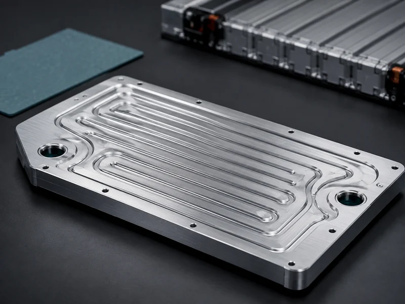
Liquid cooling plate design is the work of matching a plate structure, a material, and an internal flow path to three fixed targets: the pack’s heat load, its temperature-uniformity requirement, and the pressure-drop budget the pump and system can afford. Pin those three down first, and the structure and material choices that follow become trade-offs you can defend, not defaults you inherit by accident. The scope here is battery-pack and power-electronics cold plates: how the common structures are built, how material and flow-path choices move the thermal and hydraulic numbers, and how the plate mates to the cells. It does not cover pump and coolant-distribution-unit sizing or full pack-level thermal architecture, which sit one level up from the plate itself.
What a Liquid Cooling Plate Does in the Heat Path
In an indirect liquid cooling plate, the type this article covers, heat never crosses straight from cell to coolant. The plate wall is the conduction bridge between them, and its job is set by the interface on one face and the flow path inside. Heat leaves the cell, crosses a thermal interface material, conducts through the plate wall, and is carried away by coolant running through internal channels between an inlet and an outlet. The plate does not contact the live cell chemistry in this indirect arrangement. It works through that intermediate wall, which keeps the coolant separated from the cells and gives the packaging freedom that battery integrators design around. The verifiable chain to hold onto is cell enclosure → thermal interface material → plate wall → coolant.
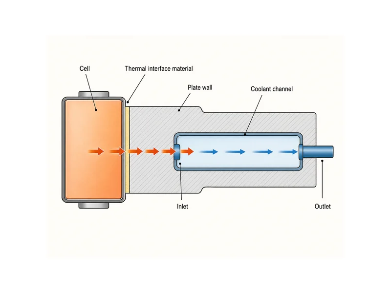
The distinction from a heat sink matters at the design stage, because the two solve different problems. A heat sink rejects heat to moving air across an extended fin surface. A cold plate transfers heat into a liquid loop that carries far more energy per unit volume, and the difference between heat sink and cold plate is what lets liquid designs stay compact under the heat densities of modern EV and ESS packs. Choosing liquid cooling is usually a decision about heat density and temperature uniformity, not simply total wattage.
Cold Plate Structures and How They Are Made
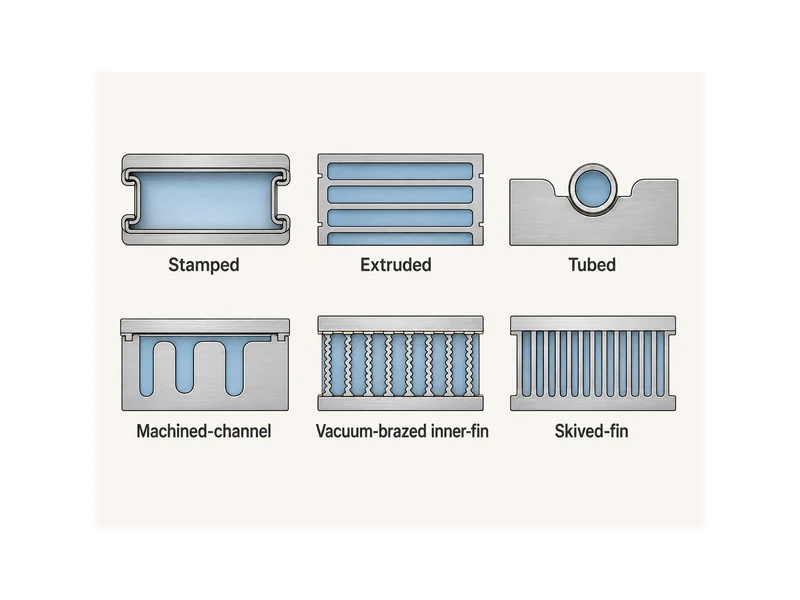
Before any channel is optimized, the manufacturing route already fixes most of the performance, weight, and cost envelope, so the structure family is the first real design fork. Each common family comes from a different fabrication method and lands in a different part of that envelope:
| Structure | How it is made | Thermal / hydraulic tendency | Cost & weight | Typical best-fit |
|---|---|---|---|---|
| Stamped | Two formed sheets sealed into a flow cavity | Moderate heat transfer, low flow resistance | Low cost, low weight | High-volume battery packs |
| Extruded | Constant-section straight channels formed in one aluminum extrusion, usually with little added channel machining | Fixed cross-section, low flow resistance | Low cost, low weight | Simple, repeatable layouts |
| Tubed | Copper or stainless tube pressed or brazed into a channeled base | Moderate heat transfer | Cost-effective | Low-to-moderate heat loads |
| Machined-channel | Milled or deep-hole-drilled passages | Tailored, non-uniform flow paths | Higher cost | Custom paths other routes cannot form |
| Vacuum-brazed inner-fin | Two plates bonded over internal fins | High wetted area, high heat flux, higher pressure drop | Higher cost | Thermal targets simpler plates miss |
| Skived-fin | Dense fins cut and stood up from the base metal in one piece, with no fin-to-base joint | High heat transfer, higher pressure drop | Higher cost | High heat flux where a joint is a liability |
Read down the table and the families sort along a few decision maxima, not a single “best” plate. The types of cooling plates trade fin density against pressure drop: skived and inner-fin designs push heat transfer up while paying a pressure-drop penalty, and simpler tubed and extruded plates hold flow resistance and cost down where peak performance is not the constraint. A tubed cold plate is often the pragmatic starting point when the heat load is moderate and the budget is tight. A brazed or skived design earns its added cost only once the thermal target cannot be met any other way.
Material Selection: Conductivity, Weight, and Corrosion
For battery packs, aluminum is the default cold-plate metal because it balances conductivity, weight, and cost, and copper is held back for the highest heat-flux spots. Bulk thermal conductivity runs around 200 W/m·K for aluminum and roughly twice that for copper. Battery-grade aluminum alloys sit lower, commonly cited in the 150–250 W/m·K range depending on the specific alloy. Treat these as ranges, not a single design constant: the alloy and temper decide the real number. Copper buys conductance at a steep weight and cost penalty, which is why it usually appears as a local insert or a targeted zone, not a whole plate.
Corrosion and coolant compatibility decide long-term reliability as much as conductivity does. Mixing dissimilar metals in the same wetted loop invites galvanic corrosion, and the coolant chemistry has to match the plate metal. The discipline of avoiding corrosion in liquid cooling systems is why designs standardize on a compatible metal set and a controlled coolant. A water-glycol mix is the common working fluid. The water-to-glycol ratio follows from the freeze protection and heat capacity the application needs, not a fixed recipe, and a surface treatment such as anodizing is often added to the aluminum for corrosion resistance.
Flow-Path Design: Pressure Drop vs. Temperature Uniformity
Once structure and material are fixed, the flow path becomes the main lever, and it sets pressure drop against temperature uniformity, the central trade of cold-plate design. Serpentine channels route coolant across the whole footprint to even out surface temperature, but the long wetted path raises pressure drop. Parallel channels split the flow to cut resistance, at the risk of uneven distribution and warmer branches. Pin-fin and microchannel cold plates add surface area and disturb the boundary layer to push heat transfer higher, and they raise pressure drop in the same move, so the goal is to buy the temperature gain at the lowest energy cost.
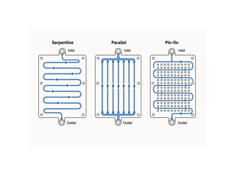
Channel geometry decides how that trade lands, so it has to be checked at the target flow rate and against the pump curve, not treated as a fixed rule. Change the hydraulic diameter, the wetted perimeter, or the channel aspect ratio, and you move three things at once: the heat-transfer coefficient, the flow distribution across the footprint, and the pressure drop. Which way peak temperature goes depends on what you hold constant, whether that is flow rate, pump power, channel count, or cross-sectional area. Confirm the direction with CFD and prototype testing under the target flow and pump curve; do not read it off a single geometry ratio. Published topology-optimization research on cold plates reports reductions on the order of a 16.9 K lower peak temperature versus conventional designs, achieved at the cost of higher pressure drop. The number is a reminder that the two objectives pull against each other and have to be balanced against the pump curve. For battery packs specifically, temperature uniformity across cells often governs the design more than the single hottest spot, because cell-to-cell spread drives aging and imbalance, and matching that goal is central to liquid cooling system design for EV and ESS packs. In a battery module, that flow-path work plays out in the aluminum water cooling plates that carry the water-glycol coolant between the cells and the loop. Channel layout and coolant distribution there set the achievable temperature spread.
Matching the Plate to Cell Format, Gap, and Assembly Stress
The plate has to fit the cell format and the interface it clamps to, so cell geometry drives the contact strategy before flow-path fine-tuning. Cylindrical cells present curved, discrete contact zones and often use inter-cell or bottom cooling; prismatic and pouch cells present flat faces that mate to a flat plate over a larger area. The contact area you can realistically achieve, not the plate’s ideal conductance, sets how much heat actually leaves the cells.
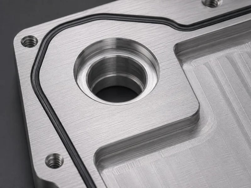
Surface flatness and the interface gap decide whether that contact is any good. Real plates and cells are never perfectly flat, so a thermal interface material fills the gap and displaces air. Its required thickness, compliance, and conductivity follow from the measured gap, the assembly stress the stack can tolerate, and the automation method used to dispense or place it. A gap-filler that is too stiff transfers assembly stress into the cells; one that is too thin cannot absorb the tolerance stack-up. At this point cold-plate design stops being a plate problem and becomes an integration problem: the gap, the assembly stress, and the interface conductivity are coupled, so they are best specified together instead of settled one after another. Trumonytechs supplies liquid cold plates alongside matched thermal interface materials, which lets both sides of that interface be sourced as one thermal solution.
Validating the Design Before You Commit
Set explicit acceptance criteria before you cut tooling, because a target that was never written down is the one a finished plate misses. Thermal and CFD simulation from the design stage lets you check maximum temperature, cell-to-cell temperature spread, and pressure drop at the target flow rate before a plate exists. Topology or parametric optimization can then trade fin and channel geometry against the pump budget while the design is still cheap to change. Write the acceptance set down first: peak cell temperature, allowable temperature non-uniformity, pressure drop at rated flow, surface flatness, and leak or burst pressure.
Mechanical and sealing checks belong in the same gate as the thermal ones. A cold plate in a battery pack has to survive vibration, pressure cycling, and thermal expansion without leaking, so confirm the mechanical, vibration, and sealing requirements that apply to your target market and pack before you rely on any single specification. Leak and proof-pressure testing on the finished plate closes the loop that simulation opens.
Conclusion
Liquid cooling plate design resolves cleanly when it is done in order: fix the heat load and the temperature-uniformity target, choose a structure and material that can meet them, shape the flow path to hit the pressure-drop budget, and only then validate against written acceptance criteria. The recurring trap is treating pressure drop and temperature uniformity as separate wins when they are two ends of the same lever, and treating the plate as finished before its interface to the cells is specified. For a battery pack, the plate and the thermal interface material act as one heat path from cell to coolant. Pairing the cold plate with a matched interface material, both of which Trumonytechs supplies, keeps the contact, coolant path, and gap consistent as a single decision.
FAQ
Serpentine or parallel channels for a battery cold plate, which trades pressure drop for temperature uniformity?
Serpentine channels favor temperature uniformity, parallel channels favor low pressure drop. A single serpentine path sweeps coolant across the whole footprint and evens out surface temperature, but the long wetted length raises pressure drop; parallel channels split the flow into shorter branches to cut resistance, at the risk of uneven distribution and warmer branches. Most battery designs blend the two or add flow balancing, choosing the mix by whether the pump budget or the cell-to-cell spread is the binding constraint.
Aluminum or copper cold plate for an EV battery pack, and when is the weight penalty worth it?
Aluminum is the default; copper is worth its weight only where a local heat flux cannot be met otherwise. Aluminum balances conductivity, weight, and cost, which matters when the plate spans a whole module. Copper roughly doubles bulk conductivity but adds large weight and cost, so it usually appears as a targeted insert at a hot zone, not a full plate. Decide by whether the thermal target is a whole-plate problem or a localized one.
Which cold plate manufacturing method fits my flow and pressure-drop target?
Match the method to how hard the thermal target pushes against the pressure-drop budget. Tubed and extruded plates keep flow resistance and cost low for moderate heat loads; machined-channel plates allow tailored, non-uniform paths; vacuum-brazed inner-fin and skived-fin plates raise heat transfer for high heat flux but carry a higher pressure-drop penalty. Start with the simplest structure that meets the target and step up only when it cannot.
How do I keep cell-to-plate contact good given surface flatness and assembly stress?
Specify the thermal interface material from the measured gap and the allowable assembly stress, not from the plate alone. Real plates and cells are not perfectly flat, so a gap-filling interface material displaces air and bridges the tolerance stack-up; its thickness, compliance, and conductivity follow from the gap, the stress the cells can tolerate, and the dispensing or placement method. A filler that is too stiff pushes stress into the cells, while one too thin cannot absorb the stack-up, so the gap and the material are specified together.
Further Reading
- A fractal geometry enhanced topology optimization design for high-performance liquid cooling plates (arXiv) — Research preprint (not peer-reviewed). Supports the point that flow-path optimization trades a lower peak temperature against higher pressure drop, and quantifies the trade for battery-relevant cold plates.
- Liquid cooling plate and battery module (US Patent 12,261,277) — US patent grant, a government primary source. Documents a worked liquid-cooling-plate-and-battery-module design and its channel arrangement, useful background on the real structures behind cold-plate selection.
Related Articles
- Data Center Chillers: Choosing Between Air-Cooled and Water-Cooled Plants — Covers where the chiller sits in the cooling chain, one level up from the cold plate.
- What is a Rack Manifold? — Explains how rack manifolds distribute coolant to servers through quick-connect couplings in a liquid-cooling loop.
- How Does Heat Pipe Cooling Work and When Should You Use It? — Covers passive heat-pipe transport and the factors that decide when it fits, an alternative to liquid cold-plate cooling.
- What is a Coolant Distribution Unit? — Explains CDUs that manage coolant flow and heat recovery, the pump-and-loop layer above the cold plate.
- Cold Plate & Welding: Thermal Management — Looks at liquid cold plates and welding for EV battery packs, including thermal expansion and aluminum-alloy plate joining.
