
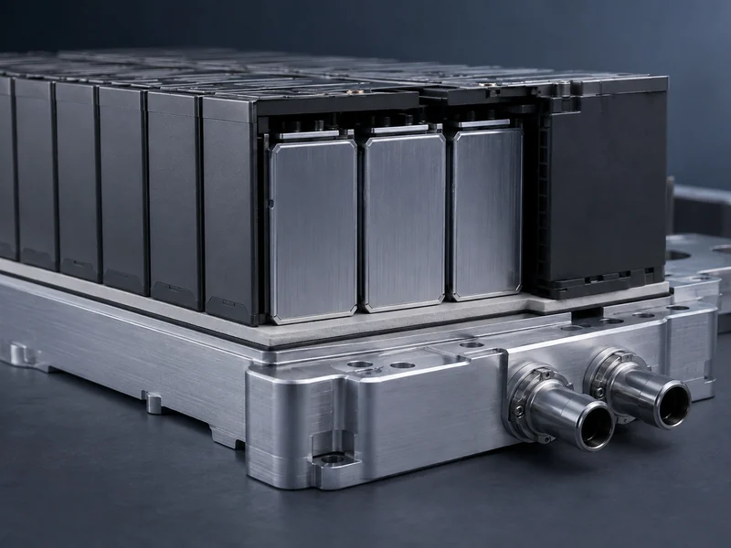
An electrically insulating thermal interface material moves heat from a cell or module into a cooling surface while blocking electrical current across that same joint. In a battery pack it sits in the narrow gap between live components and a grounded cold plate. That forces two jobs to pull against each other: conduct heat efficiently and hold dielectric isolation under voltage. This article speaks to battery-pack thermal and product engineers choosing between dielectric gap fillers, gap pads, and insulating films. It focuses on the variables that actually decide the selection, not the trade names.
What “Electrically Insulating” Means for a Thermal Interface Material
Electrical insulation and high thermal conductivity work against each other at the material level, which is the first thing to get straight before comparing products. The metals and carbon fillers that conduct heat best usually conduct electricity too, so a material optimized purely for through-plane heat transfer is often a poor insulator. A dielectric thermal interface material accepts a lower ceiling on thermal conductivity in exchange for a reliable barrier to current.
The usual way to reconcile the two is a polymer or silicone matrix loaded with ceramic dielectric fillers. Alumina (Al₂O₃), aluminum nitride (AlN), and boron nitride (BN) all conduct heat far better than the base resin while staying electrically insulating. How much a given formulation gains depends on filler type, loading, particle shape, and dispersion together, not on loading alone. Pushing any one of them also shifts flow, dielectric behavior, and cure. Because the filler is dispersed and not continuous, a ceramic-filled dielectric layer moves far less heat than a metal- or carbon-filled pad, but it keeps the electrical barrier those conductive fillers give up. Treat any single conductivity figure as tied to a specific formulation and test method, and verify it on the datasheet for the grade you intend to buy.
Two datasheet numbers carry most of the weight, and they answer different questions. Dielectric strength, quoted in kV/mm, is a material test value: it tells you how much field the material withstands before breakdown. Whether a finished joint is safe depends on that rating together with the minimum insulation thickness the bond line reaches under compression and the pack’s system voltage. Flame behavior is a separate requirement, which is why battery-grade interface materials are commonly specified to the UL 94 V-0 flammability class. UL 94 classifies burning behavior and does not by itself establish electrical insulation, so treat the dielectric rating and the flammability class as two independent checks, not one combined property.
Where Dielectric Isolation Sits in the Cell-to-Cold-Plate Heat Path
In many pack designs the dielectric layer sits at the interface between the cells or module and the cold plate, and that is the job this material class is built for. Heat generated in the cells has to cross into a liquid-cooled plate to leave the pack. Where that plate is a conductive metal tied to chassis ground and no other qualified insulation layer is in the stack, the interface material carries the isolation duty between live cell surfaces and ground. If it fails electrically, you get leakage or a short; if it fails thermally, cells run hot. That is why thermal interface materials for batteries are selected against a thermal limit and an electrical limit at once. The first design question is which layer in the insulation system actually holds off the voltage.
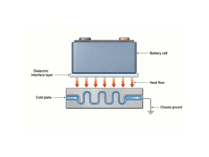
The isolation requirement changes with cell format and how the pack is built. Prismatic and pouch cells present large, relatively flat faces to cool, so a dielectric layer of even thickness carries most of the heat and the isolation duty across a wide area. Cylindrical cells concentrate contact at smaller footprints and often need a dispensed material to reach into irregular gaps. In every case the interface layer is one element of a matched heat path that also includes cold plate geometry and coolant flow, so thermal interface materials and the cooling surface they mate to are best specified together as one thermal path, not sourced in isolation.
A common point of confusion is worth settling here: an insulating interface material is not the same thing as a thermal-runaway barrier. The interface layer is meant to conduct heat continuously during normal operation while holding voltage. Barrier materials such as aerogels, mica sheets, and intumescent layers are meant to resist heat spread during a fault. Mica in particular is cited for very high dielectric strength and thermal stability in that barrier role. Selecting one for the other’s job is a frequent and expensive mistake.
Material Families That Combine Heat Transfer With Dielectric Isolation
Three material families cover most electrically insulating interface work in packs, and they differ mainly in form and how they are applied. Choosing among them is a decision about gap tolerance, assembly method, and rework more than about raw conductivity.
Dielectric gap fillers
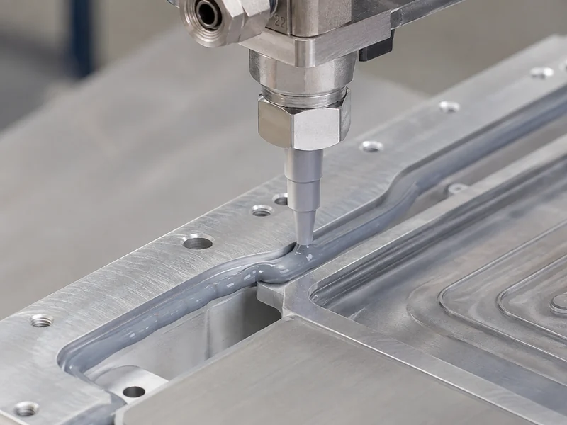
Dielectric gap fillers are dispensed as a paste or gel that spreads under compression to fill uneven gaps, which makes them the default where clearances vary across a large module. They conform to tolerance stacks that a pre-formed part cannot, and they apply low assembly force because the material flows into the gap under light load. The trade-offs are process-side: filler particles can be abrasive to dispensing equipment, and a cured filler can bond surfaces enough to complicate disassembly. Because chemistry drives cure, cleanup, and outgassing behavior, some programs move to silicone-free thermal interface materials where silicone contamination or reworkability is a concern.
Dielectric gap pads
Dielectric gap pads are pre-cut elastomer sheets, often with a dielectric layer facing the substrate, that drop into place and hold their shape. They suit designs with predictable, repeatable gaps and are easy to position and remove during assembly, which helps prototype and low-volume builds. The cost is mechanical. Pads must be compressed to a set deflection to close the interface, and the surrounding structure has to carry that force. A thicker pad also adds bond-line thermal resistance, so target gap pad thermal conductivity against the deflection your fixture can apply.
Insulating films and laminates
Thin dielectric films and laminates handle cases where the priority is a high-voltage barrier in minimal thickness and not bulk gap filling. Polyimide films, for example, carry high dielectric strength and hold up under heat and vibration. Inorganic flame-barrier laminates are a further option where arc and tracking resistance matter. Their actual thickness and performance belong to specific product grades, so read them from the datasheet. These films are the right tool when two rigid surfaces already meet closely and you need isolation without adding a compressible layer, but they do little to bridge an uneven gap on their own.
Selection Variables That Decide an Insulating TIM
The selection turns on a small set of variables that should be fixed in order, starting with the electrical requirement and ending with process fit. Locking thermal conductivity first is the common error; the dielectric and geometric constraints usually bound the problem harder. The table pairs each variable with what it governs and how to verify it.
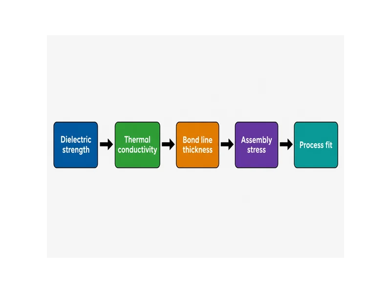
| Variable | What it decides | How to verify |
|---|---|---|
| Dielectric strength (kV/mm) | The material’s rated field before breakdown | Datasheet test value, checked against system voltage and the minimum compressed thickness |
| Thermal conductivity (W/m·K) | The material’s contribution to heat flow, before thickness and contact are added | Datasheet grade and test method, not category averages |
| Bond line thickness and gap | Joint thermal resistance and the insulation thickness left in place | Measured gap and compressed thickness, not nominal |
| Flammability class (UL 94) | Burning behavior in the pack, as a separate requirement | Rated grade, commonly V-0 for battery use |
| Assembly stress | Force the structure must carry to close the interface | Fixture and frame capacity versus required deflection |
| Cure and reworkability | Whether joints can be reopened for repair | Chemistry, cure schedule, and disassembly need |
| Filler hardness | Dispensing-equipment wear and line uptime | Filler type against pump and nozzle tolerance |
Two variables tend to be underweighted. Bond line thickness is the one that quietly changes everything. The joint’s thermal resistance and its dielectric margin are both set by the compressed thickness in the assembled pack, not by the nominal number on a spec sheet. Filler hardness is the other. Some of the harder ceramic fillers used to lift conductivity also abrade dispensing hardware and drive maintenance on a high-volume line. The hardness that helps thermally can cost you on the process side, so confirm it for the specific filler and process.
Gap Pad or Dispensed Gap Filler When Isolation Is Required
For a high-volume line with variable gaps, a dispensed dielectric gap filler is usually the stronger choice. The decision hinges on gap variation, assembly force, and rework more than on conductivity alone. A filler conforms to tolerance stacks and applies low force, so it suits automated dispensing and packs where the interface gap is not tightly controlled. Its penalties are equipment abrasion from ceramic fillers and harder disassembly once cured.
A gap pad earns its place where gaps are consistent and disassembly matters. Because a pad holds its shape and lifts back out, it fits prototypes, service-friendly designs, and lines that reposition parts during build. The constraint is that closing the interface takes real compression, and that force loads the surrounding frame. So a pad is a poor fit where the structure cannot carry that load or where the required deflection would overstress cells. Both forms can deliver dielectric isolation; the choice is set by process and geometry, not by which one is better.
Where Dielectric Isolation Quietly Breaks Down
Most isolation failures trace back to the assembled condition and not the material spec, so the verification worth doing is at the joint, not on the datasheet. In dispensed layers that can pump out or dry out over thermal cycling, the layer can thin or shift until the insulation thickness at the thinnest point falls below what the design assumed. A bench measurement of fresh material rarely shows this. A bond line squeezed thinner than intended under high assembly force can raise the local field beyond what the material was rated for. Abrasive fillers can score a dispensing tip and change the deposited bead over a production run, drifting both thickness and coverage. And treating a conductive interface material as if it were insulating, or a runaway barrier as if it were an interface layer, defeats the isolation before the pack ever ships. The practical check is to verify the joint at its real compressed thickness across the pack’s temperature range: measure the insulation margin against system voltage and confirm the bond-line thermal resistance, not the nominal datasheet values.
Conclusion
Choosing an electrically insulating thermal interface material is an ordered decision, not a hunt for the highest conductivity number. Fix the electrical requirement first, sizing it from system voltage and the thinnest compressed bond line. Then confirm the flammability class the pack demands, and only then trade thermal conductivity against the form and process that fit your gap and assembly method. The variable that most often gets missed is bond line thickness, because it sets both the joint’s thermal resistance and the insulation margin in the assembled pack, not on paper. The cleanest way to keep that honest is to treat the interface layer and the cold plate as one heat path, and to check the finished joint — insulation margin against system voltage and bond-line thermal resistance at the real compressed thickness — before the pack design is locked.
FAQ
Is a thermally conductive gap filler automatically an electrical insulator?
No. Thermal conductivity and electrical insulation are separate properties, and a filler qualifies as insulating only if its datasheet specifies a dielectric strength suited to your system voltage and thickness. Some high-conductivity interface materials use metal or carbon fillers that conduct electricity, so confirm the dielectric rating instead of assuming heat transfer implies isolation. A UL 94 rating is worth having too, but it describes flammability, not electrical insulation, so treat it as a separate line item.
How much dielectric strength does a cell-to-cold-plate TIM actually need?
The required dielectric strength scales with system voltage and the thinnest bond line the joint reaches under compression, so there is no single universal figure. Size it from the pack’s operating voltage with margin, and verify the insulation at the compressed thickness in the assembled pack, not at the nominal thickness on the spec sheet.
Do I need an insulating TIM if the cold plate already has a coated surface?
Start by asking which layer in the insulation system is qualified to hold off your system voltage, because a decorative or anodized finish is not the same as a rated insulation layer. If the coating is specified and tested to carry the isolation duty, the interface material may not have to. If it is not, the pack still needs a qualified insulation layer somewhere in that stack, and the interface material is the usual place to provide the dielectric margin. Confirm which layer owns the job instead of assuming it defaults to the TIM.
Gap pad or dispensed gap filler for a high-volume prismatic line?
A dispensed dielectric gap filler usually fits high-volume prismatic builds better, because it conforms to gap variation, applies low assembly force, and suits automated dispensing. Choose a gap pad when gaps are consistent and easy disassembly for service or rework outweighs the compression force the structure must carry.
Further Reading
- Thermal and mechanical properties of electrically insulating thermal interface materials (IEEE Xplore) — Peer-reviewed conference paper (T1). Supports the core trade-off between dielectric isolation and thermal conductivity discussed here; applies to material-level behavior, not a specific product grade.
- Battery thermal barriers in e-mobility (eMobility Engineering) — Industry technical media. Supports the distinction between electrically insulating interface materials and thermal-runaway barrier materials such as mica, aerogels, and intumescents.
Related Articles
- Which Thermal Paste Is Best? — Shows how to judge a thermal paste by target outcome and constraints, useful when a paste rather than a pad or filler is the right interface form.
- Innovations in Liquid Thermal Interface Materials for High-Heat Applications — Covers liquid TIMs such as phase-change and silicone fluids for high-heat duty, a different form factor from the dispensed and pad options here.
- Innovations in TIMs for Enhanced Thermal Management of Electronics — Explains how TIMs fill the gap between heat sources and heat sinks, the general heat-path role behind battery-pack selection.
- Is Silicone Thermal Pad Good? — Looks at silicone thermal pads’ insulation, flame resistance, and how to pick one, relevant when a pad is the candidate form.
- Silicone Thermal Pad Advantages, Limitations & Selection Guide — Details silicone pad trade-offs and failure modes such as oil bleed and outgassing that feed the reworkability decision.