
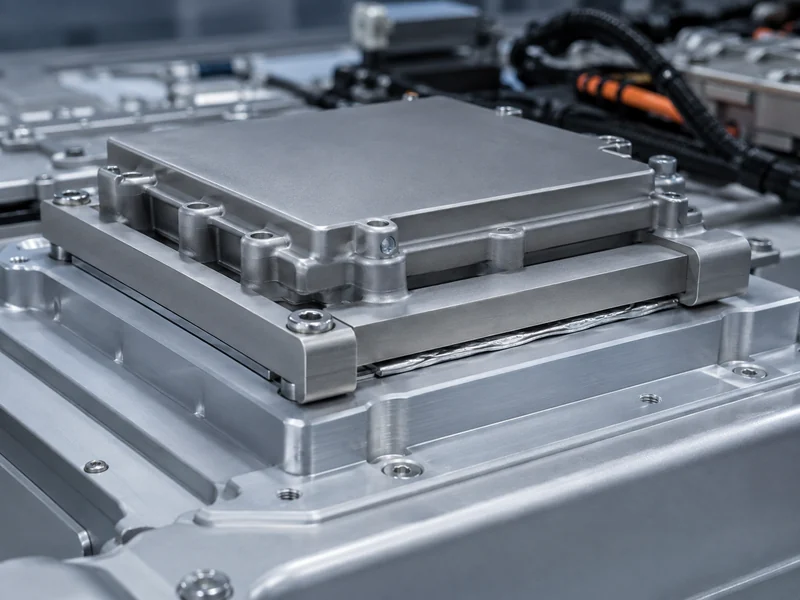
Indium is a soft, high-conductivity metal used as a thermal interface material (TIM) when a compliant solid has to carry heat across a demanding joint without pumping out or drying up. Its bulk thermal conductivity sits near 82 W/m·K, roughly an order of magnitude above filled silicones and thermal greases. It also deforms at contact pressure to fill surface irregularities instead of curing in place. This article covers what indium is as a TIM, the properties that decide whether it performs, the common forms you can specify, how it compares with paste and polymer pads, and where it fits in EV and energy-storage battery thermal management. For power-electronics and battery-pack engineers, the practical question is rarely “is indium conductive.” It is whether a metal interface is worth its cost, process, and isolation trade-offs at this specific joint.
What Indium Is as a Thermal Interface Material
Because it cold-flows instead of curing, indium behaves like a soft solder that seats a joint without ever having to melt. As a very malleable metal, it flows under clamping pressure and conforms to the microscopic roughness of both mating surfaces, closing the air gaps that dominate interface resistance in a dry metal-to-metal contact. That conformability is what lets its high bulk conductivity reach the joint, because a metal with excellent conductivity still performs poorly if it cannot wet or contact the surface.
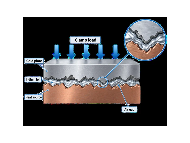
Indium sits in the “metal TIM” category alongside sintered silver and low-melt solder alloys, distinct from the polymer-based pastes, gels, and gap pads that make up most of the market. Metal interfaces offer higher bulk conductivity and lower interface resistance than polymeric options, at the cost of being harder to apply, harder to rework, and electrically conductive. Understanding indium therefore starts with a category choice: you are trading the convenience of a filled polymer for the raw heat-transfer ceiling of a metal.
Indium Properties That Drive Thermal Performance
Five properties decide an indium interface — conductivity, softness, melting point, oxidation behavior, and electrical conductivity — and each one maps to a design decision. High conductivity sets the performance ceiling; softness decides whether that ceiling is reachable at your clamp load; melting point constrains your assembly process; oxidation governs long-term stability; and electrical conductivity determines whether indium is even allowed at a given joint.
Indium’s bulk thermal conductivity is reported at roughly 81.8 W/m·K over 0–100 °C by materials supplier Goodfellow. Vendor figures for the metal range up to about 86 W/m·K depending on temperature and test method. Either way, that is far above the sub-10 W/m·K range typical of thermal greases and most silicone gap fillers, which is the core reason engineers reach for a metal interface at high heat flux. Treat the exact number as conditional on temperature and measurement conditions, not as a single fixed spec.
Softness is what converts that conductivity into a low interface resistance. Because indium yields at low stress, it can flow into surface valleys under modest pressure, so it tolerates roughness and minor non-flatness better than a rigid shim. The trade-off is that it needs adequate and reasonably uniform clamping to stay in intimate contact, so joints that cannot hold pressure undercut the benefit.
Melting point and oxidation set the operating and process boundaries. Pure indium melts near 156.6 °C — low enough that it cannot survive standard surface-mount reflow, but high enough for most non-reflow interface duty. That low melt is why it is often used as a compressible, no-cure foil instead of a soldered joint. Indium also oxidizes readily in air, so a fresh, clean surface and a stable clamped assembly matter for reliable long-term contact. On the electrical side, indium is a metal with resistivity around 8.8 µΩ·cm, so it conducts electricity and provides no dielectric isolation — a property that becomes decisive in battery packs.
Common Forms of Indium Thermal Interface Materials
The form you specify follows the joint, not the metal: its flatness, gap, and process window decide which indium TIM fits. The main options are plain foil and preforms, patterned compressible foils, reflowed solder TIMs, and indium-bearing alloys.
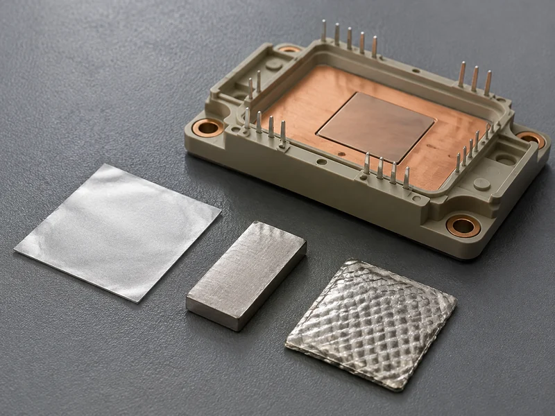
- Plain indium foil and preforms are die-cut sheets, commonly supplied at tens of microns up to fractions of a millimeter and at purities from about 99.8% to 99.999%, placed dry between heat source and sink and held under clamp load.
- Patterned or textured compressible foils are engineered to conform to rougher or slightly warped surfaces and to be handled and reworked without reflow; commercial soft-metal-alloy foils in this class are offered for TIM1.5/TIM2 duty, burn-in, and immersion cooling.
- Solder-type indium TIMs (sTIM) are reflowed to form an intermetallic bond, which gives the lowest contact resistance available but converts the interface into a permanent, non-reworkable joint sensitive to void control.
- Indium-bearing solder alloys, including low-temperature and tin-silver-indium systems, are used for package-attach where a lower processing temperature helps avoid warpage and delamination in molded power modules.
Match the form to the interface: a flat, well-clamped lid uses thin foil, a rough or warping interface uses a thicker compressible foil, and a permanent die- or package-attach interface uses a reflowed solder alloy. Foil thickness is a genuine variable, not a default, because too thin cannot fill the real gap and too thick adds bulk resistance.
Indium TIM Compared With Thermal Paste and Polymer Pads
Against paste and silicone gap pads, a metal interface trades convenience, cost, and isolation for a much higher conductivity ceiling and stable, non-pump-out behavior. Read the comparison as a trade study, not a ranking: indium wins on raw heat transfer, but it is electrically conductive, more expensive per joint, and more demanding to apply and rework.
| Interface type | Bulk conductivity | Dielectric isolation | Rework | Best-fit interface | Main limitation |
|---|---|---|---|---|---|
| Indium metal foil/preform | ~82 W/m·K (conditional) | No (conductive) | Foil: yes; reflowed: no | High heat-flux, high-reliability joints | Cost, no isolation, needs clamp/clean surface |
| Thermal paste / grease | Typically < ~10 W/m·K | Depends on filler | Yes | Small, flat, low-gap CPU/module lids | Pump-out and dry-out over cycling |
| Silicone gap pad | Low single digits typical | Usually yes | Yes | Uneven gaps needing isolation | Lower conductivity ceiling |
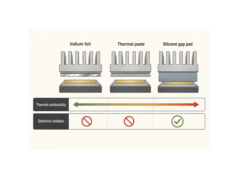
Let the constraints drive the choice; a headline conductivity number on its own tells you little. If the interface is thin, flat, and does not need isolation, and heat flux is extreme, indium’s ceiling can justify its cost and handling. If the joint needs dielectric separation or tolerates modest conductivity, a polymer pad or paste is usually the better engineering and economic choice. Those variables carry across every material family, so choosing the right thermal interface material for a given joint means weighing them together, not ranking materials in the abstract.
Where Indium TIM Fits in Battery Pack Thermal Management
Inside a battery pack, indium fits only the concentrated, isolation-tolerant heat paths, not the cell-to-plate face, because most pack interfaces need a dielectric isolation that bare metal cannot provide. In an EV or ESS pack, heat moves from cells through an interface material into a cold plate and out to the coolant. The dominant interface job is usually to fill a variable, sometimes large gap between cells or modules and the cooling surface, while keeping the cells electrically isolated from the plate. That combination is where filled-silicone gap fillers and pads normally sit, and it is where a bare metal interface is disqualified because indium conducts electricity.
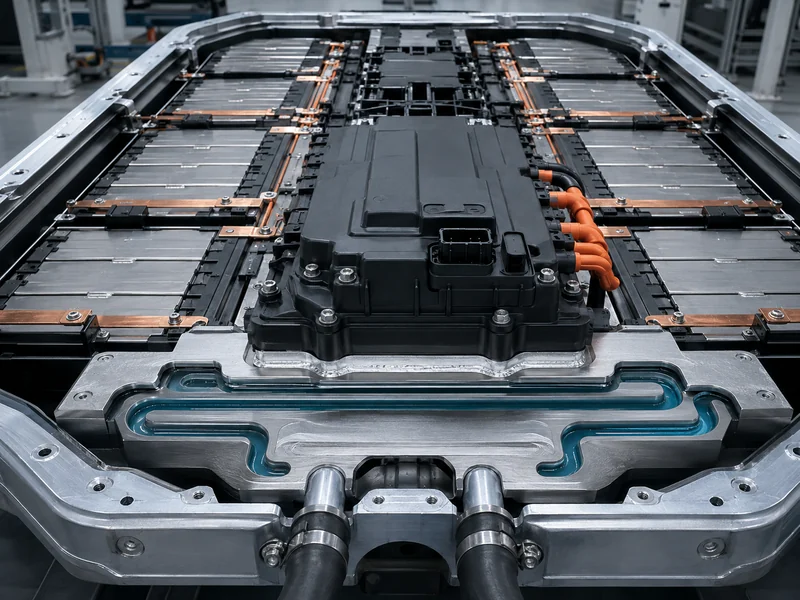
The realistic home is power-electronics attach. Inverter or BMS power-module package-attach — where heat flux is high, surfaces are flat and rigid, and the joint is already electrically defined — is where metal interfaces including indium alloys belong. These joints also drive the low-temperature solder-alloy work aimed at cutting warpage during module assembly. When you specify TIMs across a pack, the useful mental model is a portfolio: indium or metal attach at the semiconductor-to-heatsink interface, and compliant, isolating thermal interface materials for batteries at the cell-to-plate interface. Because those interfaces feed the same coolant loop, you have to select the interface and the cold-plate architecture together, not in isolation. Indium is only one option a pack designer weighs against gap fillers, structural adhesives, and phase-change materials in the broader thermal management materials family.
What to Verify Before Specifying Indium TIM
Before committing to an indium interface, verify surface condition, clamp load, gap, isolation need, and process temperature, since any one of them decides whether the metal’s conductivity is real or theoretical. Confirm the mating surfaces are flat and clean enough for cold-flow contact, that the assembly can hold adequate and uniform clamp pressure, and that the real bondline gap matches the foil thickness you intend to use.
Confirm the isolation and process boundaries early, since they can rule indium out regardless of thermal upside. Check whether the joint needs dielectric separation, in which case a bare metal foil is disqualified. If you are using a non-reflow foil, confirm your assembly temperature stays within indium’s low melting limit, and account for oxidation control and cost per joint at your production volume. Where a specific alloy or preform is proposed, take conductivity, melting range, and thickness from that product’s own datasheet, not from the pure-metal figures in this article.
Conclusion
The useful takeaway on indium is that it is a conductivity ceiling you buy deliberately, not a default upgrade over paste or pads. It earns its place at thin, flat, high-flux, isolation-tolerant joints — most often at power-semiconductor attach, not at the cell face. In return it asks for clean surfaces, real clamp load, oxidation awareness, and a bondline matched to its thickness. The single point most often misread in a battery context is isolation: indium conducts electricity, so its high thermal number is irrelevant wherever the interface also has to keep parts apart electrically. When you map interface choices onto the cell-to-coolant path, we can help match each interface material to the cold-plate architecture it feeds, so the metal option goes only where its trade-offs pay off.
FAQ
Is indium foil actually better than thermal paste for a high-power module?
Indium foil can outperform paste at a high-power module, but only when the interface suits a metal. Its bulk conductivity near 82 W/m·K is well above the sub-10 W/m·K range of typical greases, and it will not pump out over thermal cycling. That advantage only materializes on a flat, clean, well-clamped joint that does not need electrical isolation and can absorb the higher cost and handling effort.
Do I need indium TIM if my interface has large CTE mismatch and warping?
Large CTE mismatch and warping usually call for a compliant compressible interface, and a thick patterned indium foil is one option, not an automatic answer. Metal foils engineered for non-planar, warping interfaces exist for this case, but a compliant polymer gap filler may serve better where the joint also needs dielectric isolation or lower cost. Let isolation need and clamp behavior drive the choice, since warp alone does not settle it.
Does indium oxidation hurt long-term thermal performance?
Indium oxidizes readily in air, so oxidation is a real reliability variable that clean surfaces and a stable clamped assembly are meant to manage. A fresh, well-mated, and adequately loaded joint keeps the metal in intimate contact, which is why surface preparation and maintained clamp pressure matter as much as the conductivity number for long-term performance.
Is indium TIM electrically conductive, and does that matter in a battery pack?
Indium is a metal and conducts electricity, which matters a great deal in a battery pack. Because a bare indium interface provides no dielectric isolation, it is disqualified anywhere the interface must keep cells or modules electrically separated from the cold plate. It is generally restricted to already-defined interfaces such as power-module attach, not the cell-to-plate face.
Further Reading
- Indium TIM product overview (manufacturer resource) — Manufacturer technical resource. Supports the discussion of indium TIM forms such as solder TIMs, compressible foils, and metal alloys.
- Indium foil material data (materials-supplier datasheet) — Materials-supplier data page. Source for the indium thermal conductivity, melting point, and purity figures cited above, stated with their measurement conditions.
Related Articles
- New Advances in Thermal Interface Materials Enhance Electronics Cooling Efficiency — Surveys newer TIM options and trends, giving the broader material context around where a metal interface like indium fits.
- Phase Change Thermal Pad — Explains phase-change pads and their transition band, clamp pressure, and bond line, one of the alternatives weighed against a metal interface.
- Potting Compounds — A selection guide for potting compounds (encapsulants), a related protection-and-heat material family a pack designer evaluates alongside interface materials.
- Silicone Thermal Pad — Covers silicone thermal pad advantages, limitations, and selection, detailing the isolating polymer pads indium is compared against in a battery pack.
