
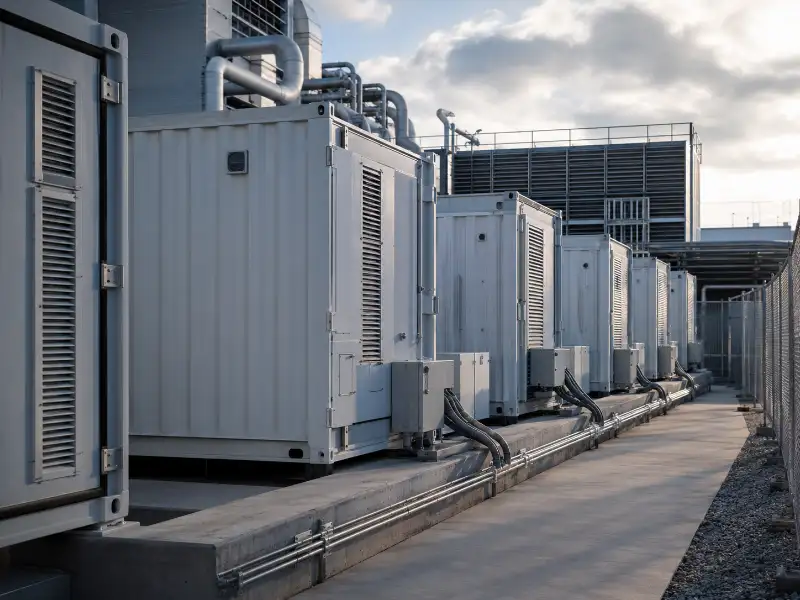
A battery energy storage system (BESS) captures electrical energy from the grid, solar generation, or wind. It stores that energy as chemical energy in rechargeable cells, then releases it on demand. Engineers and project developers evaluating BESS often focus on cell chemistry first. But lifespan depends on more than chemistry alone. Operating temperature range, inter-cell thermal variance, and thermal management integration are the variables most likely to determine whether a system performs as designed.
What a Battery Energy Storage System Does — and How Deployment Scale Shapes Requirements
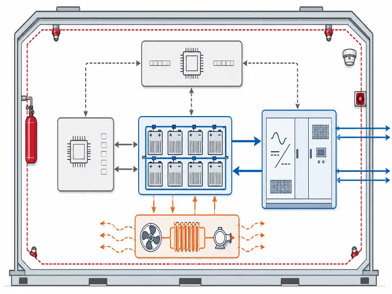
A BESS stores electricity when supply exceeds demand — during off-peak hours or peak solar generation — and discharges it when demand rises or grid power is interrupted. During the charge phase, the power conversion system converts incoming electricity to DC and feeds it into battery cells for storage. During discharge, stored DC power flows back through the PCS, which converts it to AC for grid or load delivery. Between cycles, the battery management system monitors cell voltage, temperature, state of charge, and state of health.
Deployment scale determines which engineering variables need the tightest control. Utility-scale systems commonly start in the multi-MW range and extend to hundreds of MWh. They support frequency regulation and daily peak load shifting. High cycle frequency places continuous thermal loads on the battery pack. Commercial and industrial (C&I) systems cover the tens of kWh to multi-MWh range. These handle peak shaving and backup power, often in space-constrained environments where heat dissipation is harder to achieve. Distributed and microgrid deployments introduce variable charge sources and longer autonomy requirements. Outdoor ambient temperatures in these installations can push cells outside their optimal operating window without an appropriately sized cooling strategy.
The Core Components of a Battery Energy Storage System and How They Interact
Battery energy storage system performance depends on six integrated subsystems.
| Component | Primary Function | Temperature-Dependent Risk |
|---|---|---|
| Battery modules | Store and release electrical energy via electrochemical reactions | Capacity fade and accelerated aging outside optimal operating window |
| Battery Management System (BMS) | Monitor cell voltage, SOC, SOH, and trigger protection logic | Algorithm accuracy degrades when inter-cell temperature variance is high |
| Power Conversion System (PCS) | Convert between battery DC and grid/load AC | Conversion efficiency drops as internal component temperatures rise |
| Energy Management System (EMS) | Schedule charge/discharge cycles based on grid signals and load forecasts | Scheduling that ignores thermal state can push cells outside safe operating limits |
| Thermal Management System (TMS) | Maintain cells within optimal temperature range and minimize inter-cell ΔT | Failure to control ΔT is a primary driver of uneven cell aging |
| Enclosure and fire protection | Contain the battery array; provide environmental protection, gas detection, and suppression | Inadequate ventilation amplifies heat accumulation and propagation risk |
The battery pack thermal management system is the component most commonly underspecified at the design stage. It does not dispatch power or appear in energy yield calculations. But it determines whether every other component operates within its design limits across thousands of cycles — and whether the system reaches its warranted lifespan.
Why Battery Storage Systems Often Degrade Before Their Rated Cycle Life
The most common misconception in BESS procurement is that rated cycle life is primarily a function of chemistry. Thermal runaway and thermal stress are among the strongest and most underestimated degradation drivers in BESS projects. Their impact is greatest when pack-level temperature uniformity is not controlled. They also interact with depth of discharge, C-rate, SOC window, and ambient exposure.
Battery cells age through calendar aging at rest and cycle aging during charge and discharge. Both accelerate when cells operate outside their optimal temperature window. When cell temperatures vary across a pack — a condition known as high inter-cell ΔT — cells in hotter zones charge and discharge at different rates than cooler neighbors. The BMS compensates through cell balancing. But this introduces additional charge cycles to already-stressed cells. Over time, the weakest cells set the capacity ceiling for the entire system.
When project teams select a chemistry based on rated cycle count alone, real-world capacity fade routinely outpaces the datasheet projection. We see this pattern appear within the first few years of operation. The failure mode is not the cell. It is the assumption that cells will operate at the conditions the manufacturer’s datasheet describes. BMS programming and pack-level balancing strategies depend on system architecture and should be validated with the system integrator.
Battery Chemistry Comparison: LFP, NMC, and the Thermal Constraints That Come With Each
Battery energy storage systems rely primarily on two cell chemistries for stationary applications: lithium iron phosphate (LFP) and lithium nickel manganese cobalt oxide (NMC). Each carries distinct thermal constraints that should inform both chemistry selection and thermal management design.
Typical Engineering Reference Ranges — Verify Against Cell Datasheet and UL 9540A Test Data
| Parameter | LFP | NMC |
|---|---|---|
| Optimal operating temperature | 15–35°C | 15–30°C |
| Thermal runaway onset (approximate) | ~270°C | ~150–210°C (varies by formulation) |
| Gravimetric energy density | ~120–160 Wh/kg | ~150–220 Wh/kg |
| Cycle life at rated DoD and temperature | 3,000–6,000 cycles | 1,500–3,000 cycles |
| Thermal management requirement | Moderate | Stricter; tighter temperature uniformity required |
Values are representative engineering reference ranges, not universal certification limits. Actual operating limits, thermal runaway behavior, and cycle life depend on cell supplier, cell format, SOC window, C-rate, enclosure design, and test method. Verify against the specific cell datasheet and UL 9540A test data.
LFP’s higher thermal runaway threshold and longer cycle life make it the preferred chemistry for most C&I and utility-scale stationary projects. Where safety, longevity, and total cost of ownership across a 10–15 year project life drive the decision, LFP is the standard starting point. NMC suits installations where footprint is the binding constraint — data center backup and certain maritime deployments are common examples. Neither chemistry eliminates the need for active thermal management. LFP’s wider thermal tolerance does not mean it performs equally across its full operating range. Performance in either chemistry drops sharply below 10°C.
Where Battery Energy Storage Systems Are Deployed and What Each Application Demands
Battery energy storage systems serve distinct functions across three primary deployment contexts, each shaped by different capacity profiles, discharge duration requirements, and thermal load characteristics.
- Utility-scale grid storage systems commonly start in the multi-MW range and may extend to hundreds of MWh. They support frequency regulation and peak load shifting under high cycle frequency. Outdoor utility-site installation means ambient conditions vary widely by geography and season. The thermal management architecture must be rated for the site’s full temperature range — not average conditions.
- C&I peak shaving and backup systems cover tens of kWh to multi-MWh installations. They discharge for two to four hours during peak tariff periods and hold a reserve for power continuity events. We recommend evaluating cooling architecture against the site’s documented temperature extremes — minimum winter and maximum summer — at the initial specification stage. A containerized rooftop system in a hot climate faces fundamentally different conditions than a basement installation in a temperate region.
- Distributed microgrids and off-grid installations include remote infrastructure, island grids, and behind-the-meter renewables requiring extended autonomy. Variable charge patterns and ambient temperature extremes push cells outside their optimal operating window without an active, appropriately sized cooling strategy.
How Thermal Management Architecture Determines Long-Term BESS Performance
Thermal management in a battery energy storage system spans cell-level heat extraction, coolant circuit design, and BMS integration for closed-loop temperature regulation. The choice between active and passive thermal management options should reflect power density, ambient temperature range, and cycle frequency.
| Scenario | Air Cooling | Liquid Cooling |
|---|---|---|
| Indoor, low cycle frequency, stable ambient | May be adequate | Optional |
| Outdoor container, hot or variable climate | Usually insufficient | Recommended |
| High C-rate / high power density | Usually insufficient | Recommended |
| Utility-scale daily cycling | Limited applicability | Recommended |
| Space-constrained cabinet | Depends on power density | Often recommended |
For a more detailed breakdown of each approach, see our guide to the types of battery cooling systems used in stationary storage applications.
Air cooling works for low-power-density systems in controlled indoor environments with stable temperatures. Its limits appear when cycle frequency creates continuous heat loads that convective airflow cannot remove fast enough. Cell temperature then rises between cycles rather than recovering to baseline.
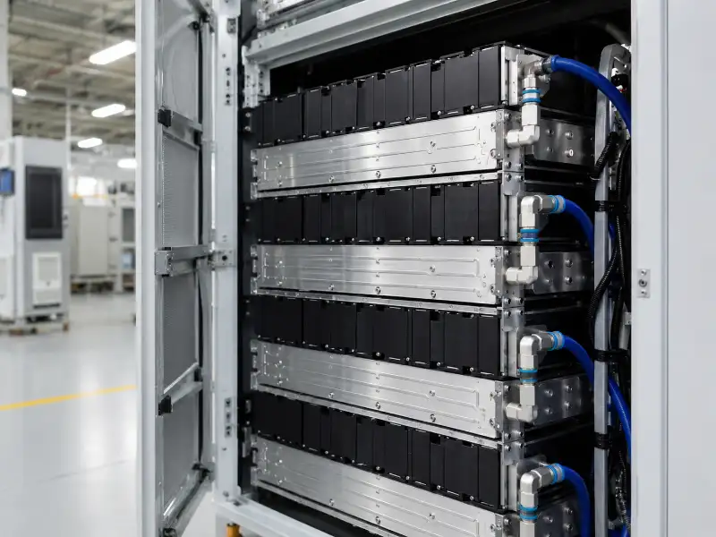
Liquid cold plate cooling extracts heat directly from the battery module surface. A coolant circuit integrates with thermal interface materials positioned between the cell and the plate. This approach achieves tighter inter-cell ΔT. Cells stay within their optimal range under sustained high-rate cycling. Research into how liquid cooling extends ESS lifespan consistently points to ΔT uniformity — not just absolute temperature control — as the dominant factor in reducing capacity fade.
Cooling does not replace fire detection, gas monitoring, electrical isolation, enclosure design, or fire propagation testing under UL 9540A. System-level safety depends on certified components, detection and suppression systems, and installation code compliance — cooling addresses thermal stress and temperature uniformity within that broader framework.
Our ESS Cooling Solutions combine liquid cold plates, thermal interface materials, and coolant circuit engineering. We validate cooling performance against each project’s specific cell format, chemistry, and deployment environment before finalizing the design.
BESS Safety Standards Every Project Team Should Verify
Battery energy storage systems fall under a layered set of standards covering component certification, system-level safety, installation approval, and fire protection compliance. Confirm alignment with applicable standards before finalizing system architecture.
UL 9540 is the system-level safety standard for energy storage systems. It covers charging and discharging procedures, fire protection requirements, and system integration. UL 9540A tests for thermal runaway propagation risk. Authorities having jurisdiction (AHJ) reference it when reviewing whether a system can be sited in a given configuration.
NFPA 855 establishes minimum requirements for stationary energy storage system installations. This includes separation distances, ventilation, detection, and suppression. IEC 62933 covers the full scope of electrical energy storage system standards. IEC 62933-1 is the reference for EES definitions, planning, installation, and safety terminology.
For engineering guidance on preventing thermal runaway in BESS at the system level, including how cooling architecture interacts with UL 9540A propagation test requirements, see our dedicated technical overview.
Thermal management design should be evaluated not only as a performance feature but also for its contribution to thermal runaway mitigation and fire propagation risk reduction. Cooling architecture decisions made early — before enclosure layout and installation spacing are finalized — carry the most design flexibility and the lowest cost of change.
Conclusion
A battery energy storage system’s performance comes down to three interdependent variables. Chemistry must match the application’s cycle profile and temperature environment. The BMS must monitor and protect individual cells accurately. And the thermal management architecture must maintain pack temperature uniformity under actual operating conditions — not just datasheet conditions.
In the BESS projects we have supported, systems with active liquid cooling specified from the design stage show more predictable capacity fade. Premature failures are less frequent than in systems where thermal management was undersized or added after installation. The exception applies to lightly cycled systems in stable, climate-controlled indoor environments — air cooling is appropriate there. For systems with high cycle frequency, elevated ambient exposure, or space-constrained installation, thermal management is not a detail to defer.
For a deeper look at the engineering principles behind liquid cooling system design for ESS thermal management, our technical guide covers coolant selection, cold plate configurations, and flow rate sizing by application type.
To evaluate thermal management options for your BESS project, share your system parameters — chemistry, pack configuration, cycle profile, and site ambient conditions. We can then assess how our ESS Cooling Solutions fit the specific requirements. The earlier thermal design enters the process, the more options remain available.
FAQ
What is the difference between a battery energy storage system and a UPS?
A BESS delivers sustained energy over hours for peak shaving, grid stabilization, or renewable storage. A UPS provides short-duration ride-through during power interruptions — typically seconds to minutes. Battery energy storage systems require active thermal management and EMS scheduling. Most UPS systems do not.
What are the main components of a BESS?
A BESS integrates battery modules, a BMS, a PCS, an EMS, a thermal management system, and an enclosure with fire detection and suppression. The most common integration failure is not a component defect — it is a disconnect between the TMS and the BMS. When the thermal management system cannot provide accurate, real-time temperature data across all cell zones, the BMS makes balancing decisions based on incomplete information. That gap is where early capacity fade usually starts.
What is the role of the BMS in a battery energy storage system?
The BMS monitors individual cell voltage, temperature, state of charge, and state of health. It triggers cell balancing and protection logic to prevent overcharge, over-discharge, and thermal events. What the BMS cannot do is compensate for a TMS that is undersized or poorly integrated. If cell temperatures are uncontrolled, the BMS receives inaccurate SOC and SOH readings, applies balancing to the wrong cells, and accelerates aging in the zones it was trying to protect. BMS performance depends on the quality of the thermal environment it is monitoring.
How long does a battery energy storage system last?
LFP systems within their optimal temperature window typically achieve 3,000–6,000 cycles before reaching 80% of initial capacity. Systems that run above 35°C regularly, or with high inter-cell ΔT, reach that threshold sooner than the datasheet projects. Actual lifespan reflects chemistry, thermal management, discharge depth, and C-rate together.
Is LFP always the better choice over NMC for stationary storage?
LFP is the default starting point for most C&I and utility-scale stationary applications. Its higher thermal runaway threshold and longer cycle life make it the lower-risk choice at project scale. NMC is appropriate where installation footprint is genuinely the binding constraint. Before finalizing either chemistry, ask your cell supplier to specify the thermal runaway onset temperature at the actual SOC level your system will operate — not at full charge. Onset temperature drops significantly at elevated SOC, and that difference affects both cooling architecture and UL 9540A compliance planning.
Does every BESS need liquid cooling?
No. Air cooling is adequate for low-power-density systems in stable indoor environments with low cycle frequency. The clearest trigger for upgrading to liquid cooling is the combination of C-rate and ambient temperature: if a system discharges at 0.5C or higher in an environment where ambient temperatures regularly exceed 30°C, air cooling will struggle to prevent inter-cycle temperature accumulation. At that point, the question is not whether liquid cooling improves performance — it is how quickly the cost of premature capacity fade exceeds the cost of the cooling upgrade.
What is inter-cell temperature difference (ΔT) and why does it matter?
Inter-cell ΔT is the temperature variance between cells across a battery pack. High ΔT causes cells to age at different rates. The BMS applies more aggressive balancing to compensate. Over time, the most-stressed cells limit total pack capacity. Controlling ΔT — not only absolute temperature — is the more precise target for thermal management design.
What standards apply to battery energy storage systems?
Key standards include UL 9540 (system-level safety), UL 9540A (thermal runaway and fire propagation test method), NFPA 855 (stationary ESS installation requirements), and IEC 62933 (EES definitions and safety). Applicable standards vary by jurisdiction. Confirm with the authority having jurisdiction during the design phase.
