
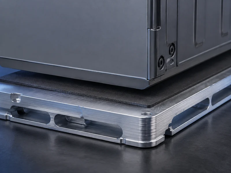
A carbon fiber thermal interface material moves heat across a joint by standing conductive fibers up through the bond line, which is what separates it from the ceramic-filled pads most battery packs still use. For an engineer routing heat from cells into a cold plate, that structural difference is the whole point: the fibers can carry far more heat along their length than any particle-filled silicone. That advantage shows up only when the fibers are oriented across the gap, not when they lie flat. The sections below cover how these materials work, where their through-plane numbers actually come from, the electrical trade-off that matters next to live cells, and how to judge whether one belongs in your pack instead of a conventional gap filler.
What a carbon fiber thermal interface material actually is
A carbon fiber thermal interface material is a polymer, usually silicone, loaded with carbon fibers that bridge the two mating surfaces it is squeezed between. The fibers do the conducting, while the matrix handles wetting, compliance, and handling. Its low hardness lets the sheet deform into the microscopic roughness of each surface. Because a single carbon fiber conducts heat well in one direction and poorly in the others, how those fibers are arranged inside the matrix matters more than how much fiber the compound contains.
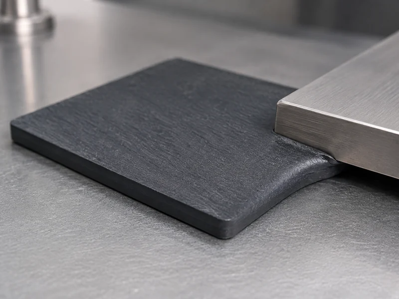
Two quite different products travel under the same name, and treating them as interchangeable is where selection goes wrong. One is a randomly dispersed short-fiber compound, where fibers point every which way and only a fraction ever align with the heat path. The other is a vertically oriented fiber array, where the fibers are deliberately stood up across the bond line to form continuous conduction channels. Knowing which of the two a datasheet describes is the first check before you compare any conductivity figure between products.
The matrix does more than bind: its softness is a working specification, not an afterthought. A compliant, low-hardness silicone lets the sheet deform under modest pressure, so the fibers actually contact both surfaces instead of tenting over high spots. That contact is what turns nominal conductivity into real heat transfer across an imperfect joint. Push hardness up to make the pad more robust and you raise the assembly force needed to close the interface, which matters when the parts on either side are battery cells that tolerate only limited stress.
Why fiber orientation, not fiber content, sets through-plane conductivity
Fiber orientation sets through-plane conductivity because a carbon fiber is strongly anisotropic: reported values put its axial conductivity near 900 W/(m·K) and its radial conductivity around 5 W/(m·K). Stood on end across the bond line, the fiber becomes a high-conductivity bridge from one surface to the other; laid flat, that same fiber does almost nothing for the heat path an engineer cares about. Adding more randomly oriented fiber raises cost and stiffness faster than it raises useful through-plane conductivity.
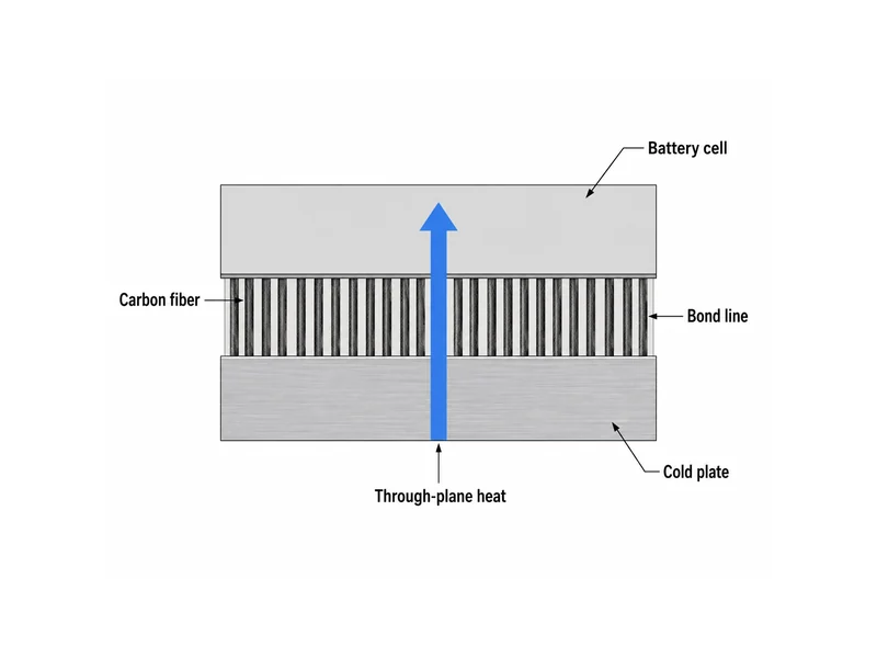
The size of the orientation effect is large and has been measured directly. In peer-reviewed work on magnetically aligned carbon-fiber silicone, through-plane conductivity rose from about 1.69 W/(m·K) with no alignment to about 11.76 W/(m·K) once the fibers were driven into vertical alignment. Both numbers come from the same 20% loading by fiber volume. The practical lesson for a datasheet reader is simple: a through-plane number means little without the orientation method behind it, because the identical formulation can differ several-fold depending only on how the fibers were arranged.
Getting fibers to stand up is the hard part, and the method shapes both performance and cost. Laboratory results often use strong magnetic fields to align fibers, while production materials rely on mechanical or flow-based orientation that is more scalable but harder to make perfect. When comparing candidates, treat the ratio of through-plane to in-plane conductivity as the real indicator of orientation quality, and confirm how a supplier measures it before trusting a single headline value.
Bulk conductivity is also only half of the heat path, because the resistance that reaches the coolant includes the two contact interfaces plus the bond line thickness the joint is held at. A well-aligned fiber network can be undercut by poor surface contact, or by a compression that never fully closes the gap. The number worth comparing is therefore the effective, in-situ thermal resistance at the real assembly pressure, not the bulk conductivity printed on a datasheet. Ask suppliers for thermal impedance at a stated pressure and bond line, since that figure folds in contact resistance the way a bare W/(m·K) value never does.
The electrical trade-off that matters next to battery cells
The same carbon that carries heat also carries current, so electrical insulation is the gating question for any carbon-fiber TIM placed near live cells. Once carbon or metal filler exceeds a percolation threshold, the material’s electrical conductivity rises along with its thermal conductivity. Ceramic fillers such as alumina behave differently, staying electrically insulating even at high loadings. That single property difference often decides the material class before thermal performance is even discussed.
In a pack, this trade-off is not academic. EV and energy-storage packs run at hundreds of volts, and any material bridging a cell surface to a grounded cold plate has to withstand that potential. That makes dielectric strength, not just conductivity, part of the admissibility test. Where the interface itself must provide isolation, an electrically conductive carbon-fiber pad is out however good its through-plane number looks, unless a separate barrier layer supplies the isolation.
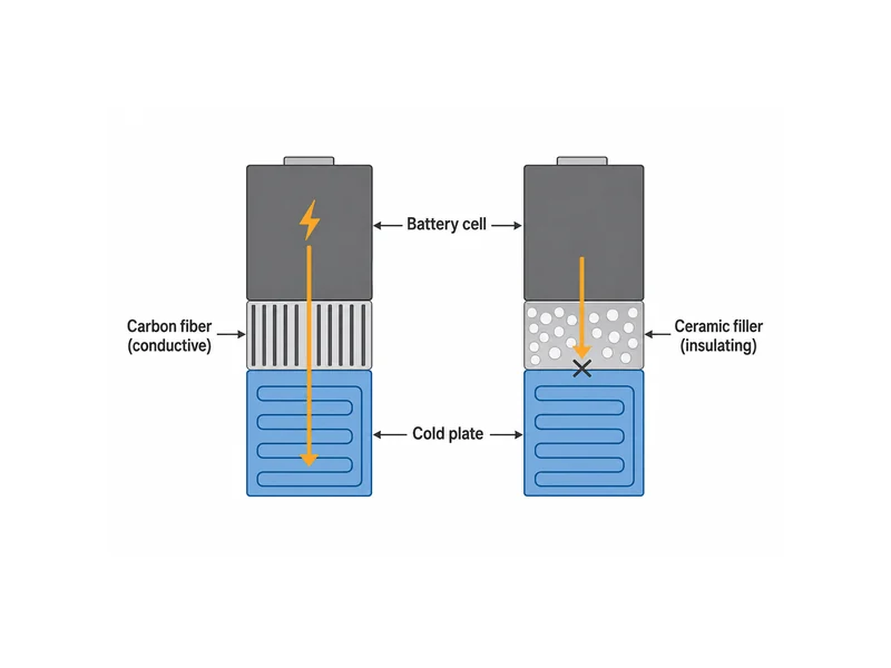
The conductive-versus-insulating divide runs through all of thermal design, not only the carbon-fiber case. The contrast between a conductive graphite sheet and an insulating thermal silicon pad maps directly onto it: high raw conductivity is worth little if the application needed the interface to hold off voltage.
Forms carbon-fiber TIMs take, and where they sit among TIM types
Carbon-fiber TIMs appear mainly as compressible pads and gap fillers, not greases, because the fiber network needs a solid matrix to hold its orientation under compression. Within the wider TIM family of greases, gap fillers, gap pads, phase-change films, and adhesives, an oriented carbon-fiber pad sits in the high-conductivity, electrically conductive corner. That corner is a small and specialized niche, not a general-purpose default.
Seeing where it fits against the alternatives makes the selection clearer, and the three carbon- and ceramic-based options engineers most often weigh line up like this:
| Interface option | Through-plane conductivity | Electrical status | Conformability | Typical fit |
|---|---|---|---|---|
| Oriented carbon-fiber pad | High; can reach double digits in W/(m·K) when well aligned | Conductive | Compliant, low hardness | High heat flux where isolation is handled separately or not required |
| Ceramic-filled gap filler | Low single digits, typical of commercial parts | Insulating | Very compliant, fills uneven gaps | Large, variable module-to-plate gaps needing isolation |
| Graphite pad or sheet | High in-plane, moderate through-plane | Conductive | Stiff and brittle | Heat spreading, not thick gap filling |
Choosing among them is a decision about the joint as much as the material, which is why choosing the right interface material for the application starts from the gap and the isolation requirement rather than from a conductivity ranking.
Fitting a carbon-fiber TIM into the cell-to-coolant heat path
Choosing a carbon-fiber TIM starts from the joint, not the material. The gap and its part-to-part variation, the flatness of the mating faces, the assembly stress the cells can tolerate, whether the interface must insulate, and how the material is dispensed all shape the shortlist before conductivity does. Get those constraints wrong and a high through-plane number never reaches the coolant, because the heat stalls at a bond line that is too thick, too stiff, or electrically excluded.
An oriented carbon-fiber pad earns its added cost where heat flux is high and isolation is either not required or provided by another layer, such as a coated cold plate or a dielectric film. For the large, tolerance-absorbing gaps typical between a module and a cooling plate, a conventional ceramic-filled gap filler often remains the pragmatic choice, because it insulates on its own, flows into uneven gaps, and dispenses cleanly in automated lines. That holds even though its through-plane conductivity is usually cited only in the low single digits of W/(m·K).
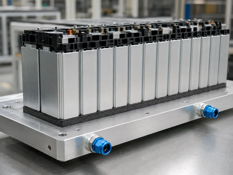
Form factor and process interact more than the conductivity number suggests. A cured-in-place or dispensed material follows automation and closes irregular gaps, but it complicates rework. A die-cut pad indexes cleanly and comes out for service, but it demands flatter surfaces and adds a fixed bond line. Whether the interface also has to bond, or simply conduct while a separate adhesive or fastener carries load, is a distinct decision from thermal conductivity. It changes which curing and structural behavior the material must have. A carbon-fiber pad that conducts superbly but cannot follow a dispensing line or tolerate the pack’s assembly stress will lose to a lower-conductivity material that fits the process.
Whichever interface material wins, it performs only as well as the cold plate behind it, so the interface and the coolant path deserve to be specified together as one heat path. Trumonytechs develops thermal interface materials and matched liquid-cooling components for EV and ESS battery packs, and pairing the interface layer with the cold plate is exactly where our TIM solutions are aimed, rather than treating the TIM as a drop-in chosen on conductivity alone.
What to keep straight about carbon-fiber TIMs
The judgment to carry away is that a carbon-fiber thermal interface material is an orientation story first and a conductivity story second. The fibers only help when they stand across the bond line, and the same formulation can differ several-fold depending on how well they are aligned. The point most often misread is treating a headline through-plane figure as portable, when it is meaningful only alongside the orientation method that produced it and the electrical status the application can accept. For a battery pack, that means resolving the isolation requirement and the real assembly gap before conductivity enters the comparison, and specifying the interface as part of the cell-to-coolant path, not in isolation.
FAQ
Is a carbon fiber thermal interface material electrically conductive?
Carbon-fiber TIMs are generally electrically conductive, because the carbon that conducts heat also conducts current once the filler forms a connected network. That rules them out wherever the interface itself has to isolate a cell surface from a grounded cold plate, unless a separate dielectric layer provides the isolation. Where isolation is required from the interface material, an electrically insulating ceramic-filled option is the safer starting point.
Carbon fiber or ceramic-filled gap filler for an EV battery cold plate?
For most module-to-cold-plate joints, a ceramic-filled gap filler is the default, because it insulates on its own and absorbs large, variable gaps, while an oriented carbon-fiber pad is reserved for high-flux interfaces where isolation is handled elsewhere. The deciding variables are the isolation requirement, the size and variation of the gap, and the assembly stress the cells tolerate, not the raw conductivity number alone.
How much does aligning the fibers raise through-plane conductivity?
Aligning the fibers can raise through-plane conductivity several-fold at the same fiber content. In peer-reviewed testing of magnetically aligned carbon-fiber silicone, through-plane conductivity increased from roughly 1.69 to 11.76 W/(m·K) at 20% fiber loading by volume once the fibers were vertically aligned, which is why orientation quality matters more than fiber percentage.
Do I need a vertically oriented carbon fiber pad, or is a standard silicone gap filler enough?
A standard silicone gap filler is usually enough when the interface must insulate and the gap is large or uneven, which describes most module-to-plate joints. A vertically oriented carbon-fiber pad is worth its cost only when heat flux is high, the gap is well controlled, and electrical isolation is either unnecessary or supplied by another layer. Confirm the isolation requirement and the actual gap before paying for orientation.
Can a carbon fiber thermal interface material conform to an uneven battery module surface?
Its conformability comes from the matrix, not the fibers, so a low-hardness silicone sheet can deform into modest surface roughness under assembly pressure. For large or highly variable module-to-plate gaps, though, a very compliant ceramic-filled gap filler still fills uneven surfaces more readily, and it does so without the electrical-conductivity concern. Match the pad’s hardness and thickness to the measured gap and flatness before assuming a carbon-fiber form can close it.
Further Reading
- High-Performance Thermal Interface Materials with Magnetic Aligned Carbon Fibers — peer-reviewed study (open access). Supports the through-plane conductivity and fiber-anisotropy figures used above, and documents how alignment method drives the result.
- Battery Thermal Barriers in E-Mobility: Innovations and Solutions — industry technical article. Context for pack-level thermal management, gap fillers, and the electrical-isolation constraints of high-voltage packs.
Related Articles
- Thermal Paste Alternative: Engineered Options and How to Choose — Reviews engineered interface materials that can replace thermal paste and the factors that drive the choice.
- What are Thermal Pads? — Explains where thermal pads sit among interface materials across EV and energy-storage packs.
- What Does Thermal Grease Do? — Covers how thermal grease displaces trapped air to cut interface thermal resistance at a joint.
- What Does Thermal Paste Do? — Shows how clamping force, surface flatness, and film thickness affect void-free coverage at an interface.
- What Is Silicone Thermal Compound? Uses & Key Factors — Defines silicone-based filled interface materials and how to select one by conductivity and electrical safety.