
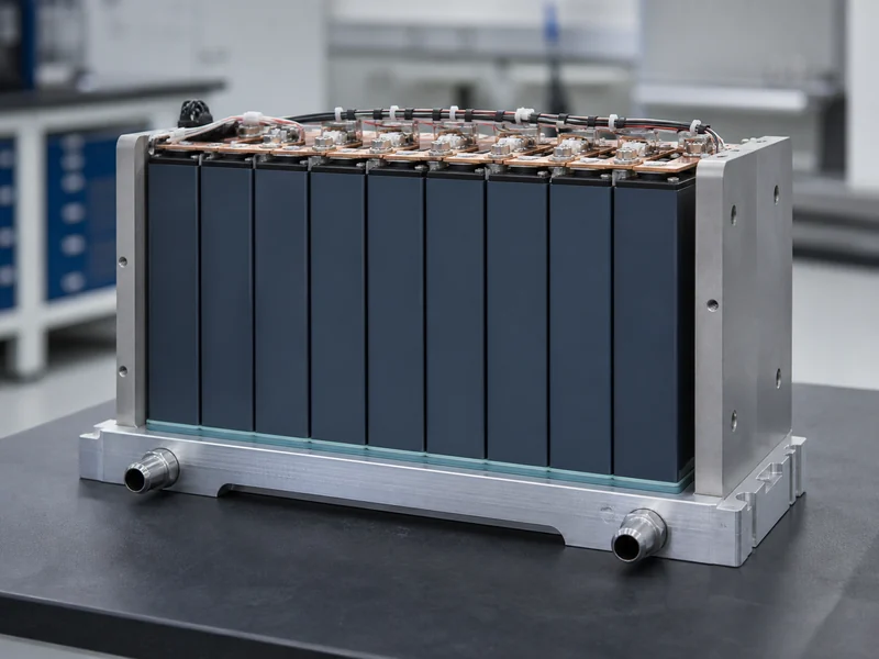
Battery module design is the set of engineering decisions that turn loose cells into a serviceable, thermally controlled block that sits between the individual cell and the finished pack. Those decisions run in a chain. The cell format fixes how cells stack and where their heat leaves; that geometry sets the interface and cold plate that carry the heat away; and the mechanical structure has to hold everything together while the cells breathe and vibrate. Get the chain right and the module is easy to cool, assemble, and service; get one link wrong and the others cannot compensate.
The module boundary sets this article’s scope: components, cell format, the cell-to-coolant heat path, mechanical retention, and the safety and validation work that confirms the design. It leaves out cell chemistry selection and full pack-level battery-management architecture, both of which sit one level beyond that boundary.
What a Battery Module Is and Where It Sits
A battery module is a serviceable sub-assembly of cells joined by interconnects, voltage and temperature sensing, and a mechanical frame, sitting one level above the cell and one below the pack. Packs are built by first grouping cells into modules and then combining those modules with the enclosure, high-voltage distribution, and cooling. That makes the module the unit most manufacturers replicate, test, and repair. Treating it as the repeatable building block is what makes quality control and service practical at scale.
Choosing a module layer at all is the first design decision, because the alternative is cell-to-pack, where cells go straight into the pack without an intermediate module. A module adds some mass and cost but buys easier assembly, sensing, and field replacement. That trade-off is why the difference between battery module and battery pack still matters even as cell-to-pack designs spread. Programs that need serviceable, scalable sub-assemblies, or that build custom battery modules around a fixed cell, generally keep the module layer; programs chasing maximum volumetric efficiency in a single fixed platform tend to drop it.
Core Components That Shape Module Design
Six recurring parts shape every module design: the cells, the busbars and interconnects, the sensing and control harness, the thermal interface, the cold plate or cooling structure, and the enclosure. Each one is a variable that pushes back on the others, so the design is really an integration problem: change any one part and the other five have to be re-checked.
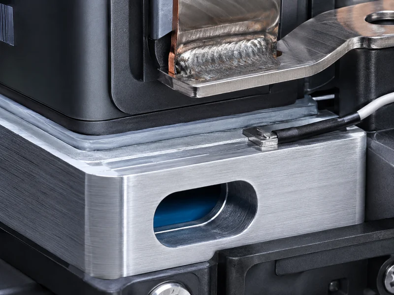
Busbars and interconnects set the current path and the ohmic heat that comes with it, so their cross-section and joint quality feed directly into the thermal budget the cooling side has to absorb. The sensing harness collects per-group voltage and temperature for the battery management system, and where those sense points sit determines whether the design can see a developing hotspot. The thermal interface and cold plate together form the exit route for cell heat. The enclosure closes the mechanical and environmental loop, carrying compression, sealing, and vibration loads. A useful check at this stage is simple: for every component decision, ask what it does to heat generation, heat removal, or heat detection, and confirm the other five parts still close.
How Cell Format Drives Module Architecture
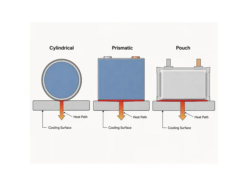
Cell format comes first among the architectural decisions because it fixes how cells stack, how they are retained, and which surface gives up heat. The three common formats — cylindrical, prismatic, and pouch — each impose a different cooling surface and retention scheme, and the EV battery module types that result look and cool very differently. Picking the format before the cooling approach avoids committing to a heat path the cell geometry cannot support; work in the reverse order and the cooling scheme can end up fighting the cell shape.
Cylindrical cells
Cylindrical cells present a curved side wall and two ends, so the heat path is usually to a cold plate at the cell ends or to a structure that contacts the sides along a line. Their rigid steel can is self-supporting and tolerant of compression, which simplifies retention, but the small line-contact area with a flat plate makes the interface material and its wetting more critical.
Prismatic cells
Prismatic cells have two large flat faces that are ideal for both mechanical retention and heat transfer, so modules commonly clamp them face-to-face and cool through a large flat interface to a cold plate. The large flat contact area is the advantage; the cost is that flatness, interface gap, and clamping pressure all have to be controlled together, because an uneven face turns into an uneven heat path.
Pouch cells
Pouch cells are flexible laminate cells with no rigid can, so the module has to supply the structure, compression, and often the flat cooling interface that the cell itself lacks. That flexibility allows dense, low-void stacking, but the low through-thickness conductivity of the pouch materials means the design leans heavily on the interface and cold plate to pull heat out at the faces or tabs.
Designing the Cell-to-Coolant Heat Path
Heat-path performance follows one chain: cell → thermal interface material → cold plate → coolant. The weakest interface in that chain governs the whole thing. Cells generate heat internally, but that heat has to cross an air-free interface into a cold plate and then into a circulating coolant, and any air gap or dry contact along the way dominates the total thermal resistance. Designing the module means sizing each link so none of them becomes the bottleneck.
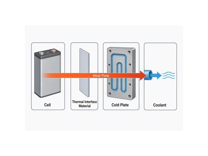
The interface layer exists to replace air with a conformable, thermally conductive path while compensating for surface unevenness and, in most designs, keeping the cell electrically isolated from the plate. Thermal interface materials are specified by through-thickness conductivity, the gap they have to fill, the assembly stress they can tolerate, and whether they cure or stay reworkable. Commercial gap fillers span roughly 0.5–4.8 W/mK depending on formulation, so the right choice is the one matched to the actual gap and stress, not simply the highest number on a datasheet. Thicker is not better here — a bigger bond line adds resistance, so the design target is the thinnest reliable layer that still fills the worst-case gap.
The cold plate carries heat from the interface into the coolant, and its material and channel layout set both temperature uniformity and pump load. Aluminum, at a thermal conductivity near 200 W/mK, is the common choice for its balance of conductivity, weight, and cost. The internal types of cooling plates and channel geometry — for example straight versus inclined channels — trade pressure drop against how evenly the coldest and hottest cells are held. This is where module-level liquid cooling system design meets the cell: the plate has to reject the module’s heat load while keeping cell-to-cell spread tight, since some high-uniformity designs target only a few degrees of delta across the module.
Temperature targets frame all of these choices. Lithium-ion cells are usually held to an operating window commonly cited around 15–35 °C, though the exact range depends on chemistry, cell format, and the aging target the program is willing to accept. Matching Trumonytechs cold plates and thermal interface materials as a set — where the plate and filler are characterized together — is what keeps the modeled heat path close to the built one.
Structural Load, Cell Swelling, and Enclosure Constraints
Mechanical design has to hold the cells under controlled pressure while accommodating swelling and vibration, without breaking the thermal interface it depends on. Prismatic and pouch cells grow measurably over life and across state of charge, so the retention scheme — end plates, bands, or a structural enclosure — must apply enough compression to keep interfaces closed while leaving room for that growth. Too little pressure opens the thermal path; too much stresses the cells and the interface material.
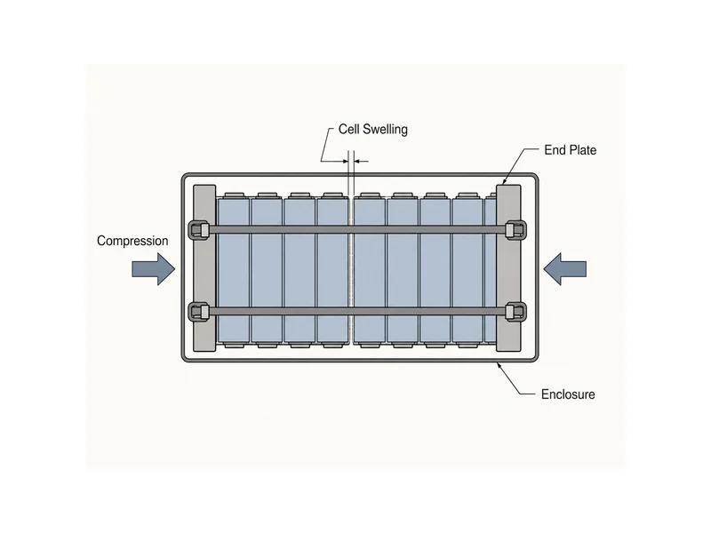
Structural bonding and sealing add the second half of the mechanical picture. Structural adhesives can bond cells or modules into a stiff, load-sharing assembly, which cuts fasteners and mass but commits the design to a bond that has to survive vibration and thermal cycling. Enclosure sealing then has to hold against ingress and, in a fault, internal pressure, with sealing validation in simulation often spanning internal pressures on the order of 100–250 bar. Whether a given design needs that margin depends on its venting strategy and cell chemistry, so the number is a modeling input, not a universal spec.
Safety, Thermal Runaway, and Validation
Safety design starts from one assumption: a single cell can fail. The goal is to keep that one failure from cascading through the module. That means thermal barriers between cells or groups, defined vent and gas paths, and electrical segmentation so a local fault does not propagate, all of which is why battery protection at the cell, module, and BMS level is built into the design from the cell up. Propagation resistance is a design target, not a coating applied at the end.
Standards give the design its acceptance framework. Industry-referenced ones such as UL 2580 for EV batteries and UL 9540A for thermal-runaway propagation testing, along with UN 38.3 for transport, are the usual references engineers design toward; the specific edition and applicability should be confirmed for the target market and application, never assumed. Validation then closes the loop with physical and virtual testing: module thermal mapping, coolant-flow and pressure-drop checks, hot- and cold-chamber and fast-charge cycles, vibration and shock, leak testing, and propagation or abuse testing. A design is only as trustworthy as the coolant-flow and propagation tests that confirm the heat path and the containment actually behave as modeled.
Conclusion
The core judgment to take away is that battery module design is an integration problem, not a sequence of independent choices: cell format, the cell-to-coolant heat path, and mechanical retention are coupled, and a change to any one ripples into the others. The point most often misread is that cooling can be bolted on after the module is laid out — in practice the format and the retention scheme have already decided how well heat can leave, and the interface and cold plate can only work within those limits. Engineers who lock the cell format first, then size the heat path, then confirm the retention keeps that path closed under swelling and vibration, end up with modules that behave in the field the way they did in the model. Where a design needs the plate and interface material characterized as a matched set, Trumonytechs works from the cell-to-coolant path to keep the built heat path close to the intended one.
FAQ
Do I need liquid cooling, or is a cold plate with a thermal pad enough for prismatic cells?
The answer depends on the heat load and uniformity target, not the cell format alone. A cold plate with a well-matched interface pad can handle moderate loads, but sustained high-power or fast-charge duty, or a tight cell-to-cell temperature target, is usually what pushes a design toward active liquid cooling through that plate. Size the expected heat load and the allowable temperature spread first, then decide whether passive conduction to the plate is enough or the plate needs circulating coolant.
How thick should the thermal interface material be between the cells and the cold plate?
Aim for the thinnest layer that still fills the worst-case gap, because added thickness adds thermal resistance. The right value is set by the real gap between the cell and plate, the flatness and tolerance stack of both surfaces, and the assembly stress the cells can tolerate, so the material and the mechanical design set it together; there is no single correct thickness to copy from a datasheet. Verify it against the actual measured gap, not a nominal one.
When is a module still worth it instead of going cell-to-pack?
A module layer is worth it when serviceability, sensing, and scalable sub-assembly matter more than squeezing out the last of the pack volume. Cell-to-pack raises volumetric efficiency by removing module structure, but it makes repair and reconfiguration harder, so programs that value field replacement, reuse across platforms, or simpler quality control usually keep the module. Weigh the mass and volume you would save against the service and manufacturing flexibility you would give up.
What temperature uniformity should a battery module target?
Most designs work to hold cells within the commonly cited 15–35 °C operating window and to keep cell-to-cell spread small, with high-uniformity modules targeting only a few degrees of delta. The exact target depends on chemistry, expected aging, and duty cycle, so treat tight uniformity as a design goal validated by thermal mapping, not a guaranteed figure. Confirm the achieved spread on a built module under a representative load case.
Further Reading
- Battery Thermal Management for EV Battery Packs — engineering reference. Supports the operating-temperature window and the cooling-architecture trade-offs discussed in the heat-path section; confirm any standard’s current edition before design use.
- Thermal Management Systems for EV — technical research overview. Backs the range of cooling methods and the heat-load context in the safety and validation sections; frames individual performance figures as source-specific.
Related Articles
- What Is an Energy Cell? — Defines the energy-type cell and how its structure and thermal behavior shape TIM selection, the cell-level layer beneath module design.
- Understanding What Are Cold Plates in Battery Thermal Management — Breaks down what cold plates are and how their internal channels move coolant, expanding on the cold plate in the heat-path section.
- What Is TEC Cooling? — Covers thermoelectric (Peltier) cooling as an alternative when a module needs precise, reversible temperature control.
- EV vs ESS Battery: Key Differences & Thermal Management — Compares EV and ESS batteries by chemistry and thermal strategy, useful when a module targets one application over the other.
- How to Choose a Battery Energy Storage System Configuration — Walks through sizing an ESS configuration, the pack-and-system level a module feeds into.
