
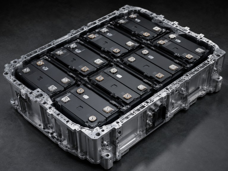
Battery engineers working on long-range EV packs, grid-scale storage systems, and high-capacity consumer electronics will encounter the energy-type cell as the default cell choice. The selection decision looks straightforward: higher Wh/kg means more range or runtime per kilogram of pack weight. In practice, the design consequences of that choice — particularly for thermal management and interface material specification — are regularly underestimated at the early stages of a program.
The core issue is not that energy-type cells are difficult to work with. It is that their thermal behavior differs fundamentally from the power-type cells many engineers have more direct experience with. Thermal management strategies that work well for high-rate power applications tend to underperform when applied to sustained energy delivery. The failure mode often surfaces gradually — over hundreds of charge-discharge cycles — rather than immediately after first assembly.
This article covers the engineering definition of an energy cell, how it differs structurally and thermally from a power-type cell, and what those differences mean for thermal interface material selection in energy-cell pack programs.
What Is an Energy Cell in Battery Engineering?
An energy cell — more precisely an energy-type cell or high-energy cell — is a lithium-ion cell designed to store the maximum amount of energy per unit weight or volume. It achieves this through thicker active material layers on each electrode and thinner current collectors, accepting higher internal resistance and a lower peak discharge rate as a result. Energy-type cells are the standard choice for applications where total stored energy determines system value: long-range EV packs, grid-scale stationary storage, and consumer electronics where runtime takes priority over burst power delivery.
The term is an industry convention, not a classification formally defined in IEC, UL, or equivalent standards. Different suppliers use varying terminology — always verify against the specific cell datasheet rather than the product label alone.
Energy-type cells are distinct from power-type cells, which prioritize peak current delivery over energy density. The two types share the same basic lithium-ion chemistry but differ in electrode design, internal resistance, C-rate ceiling, and thermal behavior. Specifying the wrong type for a given discharge profile is a common cause of thermal and degradation failures. We see this regularly in early-stage pack development — most often when cell sourcing decisions are made on energy density figures before the thermal and C-rate implications have been worked through.
Note on search intent: “Energy cell” also refers to game mechanics (Minecraft, Applied Energistics) and science-fiction devices. This article covers lithium-ion battery cells in engineering applications only. It does not apply to fuel cells, hydrogen systems, or biological energy processes.
Why Energy-Type Cells Present a Different Thermal Challenge
Engineers familiar with power cells tend to underestimate the thermal demands of energy-type cells. Power cells generate rapid, obvious heat at high C-rates. Energy-type cells generate heat more slowly — but over longer periods and from greater electrode depth. Three mechanisms drive this:
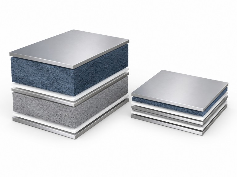
- Higher internal thermal resistance: Thick active material layers extend the heat conduction path from the electrode core to the cell surface. Heat reaches the cooling interface more slowly than surface readings suggest.
- Cumulative heat over long discharge cycles: A 100 Ah energy-type cell at 0.5C for two hours accumulates significant total heat, even at a low instantaneous rate. Thermal design must handle that sustained load, not just the peak.
- Non-uniform temperature distribution: Thick electrodes develop steeper internal temperature gradients. Cell surfaces may appear within acceptable limits while electrode cores exceed degradation thresholds.
Surface temperature monitoring alone does not confirm core thermal behavior. In programs where a power-cell thermal design is carried over to an energy-cell platform without reassessment, we typically observe that the gap filler selection — often a thinner pad optimized for transient heat events — fails to maintain consistent interface resistance under sustained discharge. The surface temperature remains within spec while cell core temperature gradually drifts beyond the rated operating window, producing capacity fade that is often misattributed to the cell rather than the interface.
How Energy-Type Cells Are Structured
Energy-type cells concentrate active material per unit volume. At the cell level, typical energy density varies by chemistry:
- NMC / NCA high-energy cells: commonly ~200–260 Wh/kg for mainstream commercial products; nickel-rich designs are reported higher in some product lines
- LFP energy-type cells: typically ~140–190 Wh/kg depending on format, generation, and supplier
Cell-level and pack-level energy density are not interchangeable. Always verify against the specific cell supplier datasheet. Energy density also varies by cell format — cylindrical, prismatic, and pouch cell formats each carry different dimensional tolerances and thermal management implications.
Four structural features define energy-type cells:
- Thicker active material layers: more lithium-intercalation material per cell
- Thinner current collectors (copper and aluminum foils): reduced inactive mass
- Low-to-moderate C-rate operating envelope: the exact rated limit must follow the datasheet, thermal design, SOC window, and cycle-life target
- Higher internal resistance: electrode thickness is one contributing factor; porosity, tortuosity, electrolyte transport, tab design, and SOC also play a role
Energy-Type Cell vs Power-Type Cell: When to Specify Which
| Parameter | Energy-Type Cell | Power-Type Cell |
|---|---|---|
| Energy density (cell-level) | NMC/NCA: ~200–260 Wh/kg; LFP: ~140–190 Wh/kg | ~100–200 Wh/kg (chemistry-dependent) |
| Continuous C-rate | Low-to-moderate; rated limit per datasheet and thermal design | Higher continuous or pulse rates; varies by chemistry, format, and cooling |
| Internal resistance | Higher | Lower |
| Electrode thickness | Thicker active material | Thinner active material |
| Primary design priority | Maximum stored energy | Maximum instantaneous power |
| Thermal risk if misapplied | Heat accumulation and accelerated aging under excess C-rate; thermal runaway risk in sustained over-discharge | Oversized pack with poor energy density for range-critical applications |
Energy-type cells suit: Long-range EV battery thermal management applications prioritizing driving range, grid-scale stationary storage requiring maximum energy per installation footprint, and consumer electronics where runtime matters more than burst output.
Poor fit: High-acceleration drivetrains, industrial power tools, and grid-support applications requiring short high-power bursts. A cell selected on energy density alone may degrade faster if the discharge profile consistently exceeds its rated C-rate.
TIM Requirements for Energy-Type Cell Packs
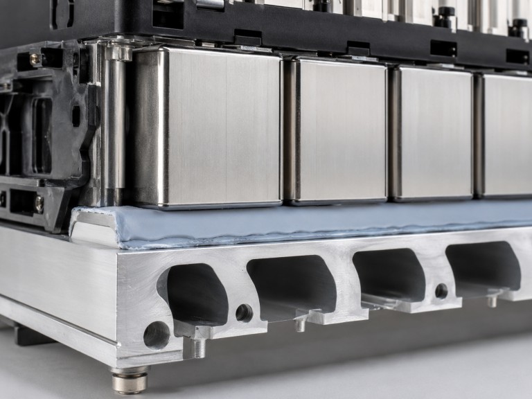
The thermal behavior of energy-type cells drives specific requirements for the thermal interface materials bridging cells to cooling structures. Requirements also shift by cell format — large-format prismatic and pouch cells carry greater dimensional variability than cylindrical cells, which directly affects gap filler compressibility specification.
- Gap pad thermal conductivity: Battery pack gap fillers commonly fall in the 2–10 W/m·K range. Select based on total interface thermal resistance at compressed bond-line thickness — not conductivity rating alone.
- Compressibility across dimensional tolerance: The gap filler must accommodate cell-to-cell height variation against the battery cold plate surface without leaving thermal voids or over-compressing cell housings.
- Long-term conformability: Sustained moderate heat flux over long discharge cycles places different demands on TIM stability than short power pulses. When gap fillers are qualified on initial datasheet values alone without compression set testing, we find that interface thermal resistance increases measurably after extended thermal cycling in sustained-discharge applications — a degradation pattern that does not appear in short-duration power-cell qualification protocols and is often only identified during pack-level aging validation.
- Outgassing compatibility: In sealed modules, volatile emissions from thermal interface materials for battery packs matter regardless of cell chemistry. LFP cells have a higher thermal runaway onset temperature than NMC or NCA — but sealed module outgassing evaluation remains part of a complete qualification process.
We align TIM selection to steady-state discharge conditions in every energy-cell pack program. Applying power-cell sizing assumptions to energy-cell applications consistently leads to underperformance where it matters most.
Conclusion
In energy-type cell packs, reliable thermal performance comes from sizing TIM selection to steady-state discharge conditions. Worst-case pulse assumptions from power-cell design do not transfer directly. Mismatches between actual discharge profiles and TIM selection assumptions are a leading cause of premature thermal degradation. The issue is rarely the component itself.
At Trumonytechs, we develop liquid cooling plates and thermal interface materials for Battery Pack Thermal Management applications. In energy-type cell programs, we verify TIM thermal conductivity, compressibility, and compression set against actual pack operating conditions — not catalog values alone. Share your cell format, gap geometry, stack pressure, C-rate profile, and target operating temperature window. Our team will confirm material fit and identify which variables need physical validation before production quantities are committed.
FAQ
What is an energy cell?
An energy cell — more precisely an energy-type or high-energy lithium-ion cell — is a cell designed to store the maximum energy per kilogram (Wh/kg) or per liter (Wh/L). It uses thicker electrode layers and thinner current collectors, accepting higher internal resistance and a lower peak discharge rate in return. Energy-type cells are used in long-range EV packs, grid-scale storage, and consumer electronics where runtime matters more than burst power.
What is the difference between an energy cell and a power cell?
An energy-type cell maximizes Wh/kg or Wh/L through thicker electrodes and a low-to-moderate C-rate envelope, at the cost of higher internal resistance. A power-type cell does the reverse — thinner electrodes and lower resistance enable high peak current, at the cost of energy density. They are not interchangeable. Choosing the wrong type for your discharge profile is a common cause of thermal and degradation failures.
Why are energy-type cells harder to cool?
Thick electrodes increase internal thermal resistance. Heat from the electrode core reaches the cell surface slowly. Long discharge cycles at moderate C-rates also build up substantial total heat, even when instantaneous rates look low. Surface sensors may not capture the core-to-surface temperature gradient. Systems sized for peak power pulses will underperform in sustained energy-delivery applications.
What should I prioritize when selecting a TIM for an energy-cell pack?
Steady-state thermal conductivity, compressibility across the cell array’s dimensional tolerance, and long-term conformability under clamping pressure are the primary criteria. Compression set over thermal cycling and outgassing compatibility for sealed modules also matter. Base the final selection on total interface thermal resistance at compressed bond-line thickness — not conductivity rating alone.
Can the same TIM work for both energy-type and power-type packs?
A TIM may be physically compatible with both. But performance requirements differ. Power-cell packs generate short, high-intensity heat pulses. Energy-cell packs impose sustained moderate heat flux over longer periods. Evaluate TIM candidates against the specific C-rate profile and thermal cycling conditions of each application. Do not assume cross-application compatibility.
