

A battery liquid cooling system circulates coolant through sealed cold plates and channels that sit against the cells, moving heat away far faster than air can for a given volume. In the sealed indirect architecture this overview focuses on, the coolant never touches the cells directly. Heat travels from cell to thermal interface material to the cold-plate wall, and only then into the coolant. That heat path is why liquid cooling has become common in high-power electric-vehicle and energy-storage packs. Rising energy density and fast charging there generate more waste heat than fans and heat sinks handle well.
Heat loads climbed past what natural convection and heat sinks could remove as drivetrains, supercharging, and fast charging advanced. The industry moved toward liquid cooling for its higher heat capacity and more even cell temperatures. This is one of the big challenges for battery thermal management that passive methods struggle to meet at high power. As a thermal management specialist, Trumonytechs designs the cold plates and thermal interface materials that carry heat along this cell-to-coolant path. The notes below tie each concept back to where those components sit in a real pack.
Liquid vs. Air Cooling for EV Battery Packs
Liquid cooling generally outperforms air cooling because liquids carry more heat per unit volume. That allows faster heat removal and more even temperatures across the pack. Water and water-glycol mixtures have several times the specific heat capacity of air, so a modest coolant flow can absorb heat that a large, noisy air volume would be needed to match. That advantage is strongest during high-power driving and fast charging, when heat loads peak.
Temperature uniformity is the second reason liquid cooling is preferred, and it matters as much as raw cooling power. A well-designed liquid loop spreads cooling evenly across modules and limits the local hotspots that age cells unevenly. Fan-and-duct air paths tend to cool inlet cells more than outlet cells, so keeping the cell-to-cell temperature spread small is a core design target. Lithium-ion packs run most efficiently between 15 and 35 °C, according to a 2025 technical review in *Global Challenges*. A liquid loop is what holds a pack inside that band under load.
Real packs show the pattern. Production EV packs commonly use a liquid-glycol loop to manage battery heat during high-speed driving and fast charging, as the peer and manufacturer sources reviewed here describe. How much a given system helps depends on load, ambient temperature, coolant flow, and the temperature-difference target the design is tuned to. Liquid systems are also quieter than fan-driven air cooling, since a pump moves the heat instead of high-volume airflow.
Applications of Liquid Cooling Systems Across Industries

Liquid cooling is used most heavily in EV and energy-storage battery packs, with high-heat-flux electronics as a related case that shares the same driver. Each application faces heat densities that air cooling can no longer serve, but they differ in temperature targets, reliability requirements, and integration constraints.
In electric vehicles, the power battery is the core of thermal design because its temperature directly affects range, efficiency, and safety. Lithium cells wired in series and parallel into a battery module are sensitive to temperature during charge and discharge. They generally need to stay in a moderate band to protect both safety and cycle life. Liquid cooling suits that requirement with high heat capacity, low flow resistance, and the option to run heating and cooling circuits as energy density and charge rates rise.
In energy storage, liquid cooling systems are equally important because large installations dissipate significant heat during high-power charge and discharge cycles. Holding a stable temperature can help prevent overheating and support reliable service life, though the actual gain depends on cycle rate, ambient conditions, and how the loop is sized. High-heat-flux applications such as data centers and high-performance computing follow the same logic. Compact liquid loops reject large heat loads in a small footprint where air cooling falls short. Other duty cycles, from electric aircraft to high-power motorcycles, are beginning to adopt coolant-based heat transfer. Their load and reliability constraints differ from an EV pack and should be evaluated on their own terms.
Components of the Battery Liquid Cooling System
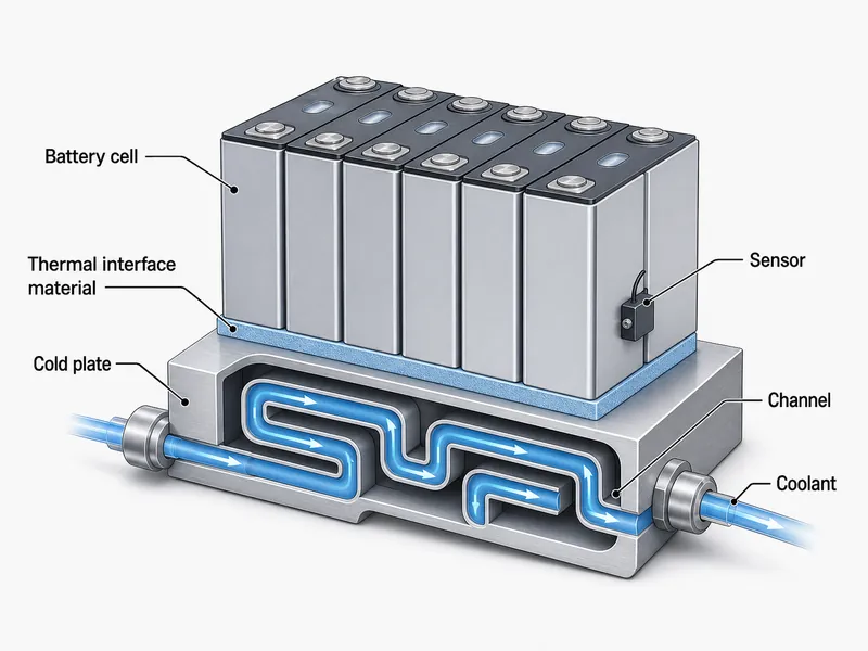
A battery liquid cooling system is organized around four required functions: absorb heat, transport it, reject it, and control it. Optional hardware beyond those functions depends on the vehicle or ESS architecture. Separating function from hardware makes it easier to judge where a specific design will hold up.
The liquid cooling plate is the heat-absorbing component, usually made from high-conductivity aluminum or copper with internal channels. Coolant passing through those channels takes up heat conducted from the cells, so plate flatness and channel layout largely set how evenly the pack is cooled. Cell format and module geometry drive this choice directly. Cylindrical, prismatic, and pouch cells each present a different contact face and pressure-drop profile, which changes where channels run and how the plate is clamped. The way plates and channels are arranged in the broader liquid cooling system design shapes temperature uniformity as much as the coolant does.
The circulation system transports the coolant and includes channels, an electric pump, and connecting lines. Pump sizing against loop pressure drop decides whether every module sees enough flow at peak load, so pressure drop and pump power are the variables to check here. A heat exchanger or radiator rejects the collected heat to ambient air. A cooling fan, when present, is the air-side of that heat exchanger, not a separate backup loop. The control system holds cells in range by adjusting flow in real time, using temperature sensors, a control unit, and actuators. Optional elements such as a three-way valve or a shared drive-electronics branch appear in some architectures and not others.
Between the cell and the plate sits the thermal interface material, and its selection is a decision variable in its own right. Gap thickness, surface flatness, assembly stress, and whether the joint needs curing or structural bonding all determine how much heat actually crosses into the plate. Trumonytechs’ interface materials and cold plates work together at this point along the cell-to-coolant path. Matching the interface material to the gap and assembly method is as important to uniformity as the plate itself.
Cooling Fluid Selection
Coolant choice is a trade-off between thermal performance and electrical safety. High heat capacity, low viscosity, and chemical stability have to be weighed against insulation, corrosion behavior, and maintenance. The best liquid for cooling in one system can be wrong in another. The table below compares common options as a starting point; toxicity, material compatibility, and flammability remain formulation- and SDS-specific.
| Coolant Type | Thermal Conductivity | Viscosity | Cost | Toxicity (formulation-dependent) | Insulation | Key Characteristics |
|---|---|---|---|---|---|---|
| Water | High | Low | Very Low | Low | Non-insulating | Excellent heat capacity and conductivity; must be kept clear of live parts and managed for corrosion |
| Water/Glycol Mixture | Moderate | Moderate | Low | Varies by glycol: ethylene glycol is toxic, propylene glycol is lower-toxicity | Non-insulating | Higher boiling point and freeze protection; concentration and additives set the exact properties |
| Mineral Oil | Moderate | Low | Moderate | Low, product-specific | Insulating | Good stability and insulation; flammability is the boundary condition to check |
| Fluorinated Fluids | Moderate | Low | High | Product-specific (check SDS) | High insulating | Strong insulation and thermal stability; higher cost and environmental/compliance factors to verify |
Water is used where the loop does not require electrical insulation, such as HVAC and some industrial systems, and it is kept clear of electrical parts. Water/glycol mixtures are commonly used in automotive and EV loops because freeze protection and a higher boiling point hold up across temperature extremes. The specific glycol and concentration change the toxicity and viscosity you design around. Mineral oil may be selected where insulation matters, including some transformer and immersion applications, with flammability as the limiting factor. Fluorinated fluids may be selected for immersion cooling that needs strong insulation and stability, at higher cost. Organize the choice around freeze point, boiling point, viscosity, electrical conductivity, corrosion inhibition, seal compatibility, and maintenance interval instead of a single “best” label.
How the Liquid Cooling Loop Moves Heat
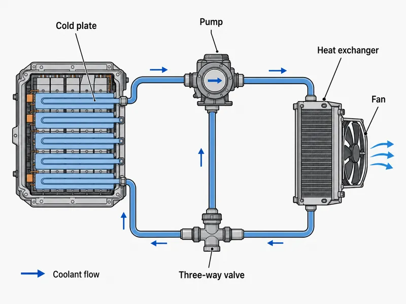
A liquid cooling loop keeps components in range by circulating coolant through a repeating heat path. The sequence below is a representative indirect cold-plate topology; the actual plumbing order depends on the vehicle or ESS architecture. The core functions of absorb, transport, reject, and control stay the same even when the hardware differs.
- Heat absorption: coolant in the cold plates takes up the heat the cells generate under load, through the interface material and plate wall.
- Heat transport: the pump drives the warmed coolant through the loop so flow stays continuous under peak load.
- Heat rejection: the coolant passes through a heat exchanger or radiator, releasing heat to ambient air, with a fan on the air side when one is fitted.
- Optional electronics cooling: in some architectures the same loop also cools drive and control electronics on a shared branch.
- Temperature regulation: a valve, often a three-way solenoid valve, routes coolant by demand between the pack and an auxiliary path.
- Circulation: the cooled coolant returns to the plates and the cycle repeats.
Compared with air cooling, this closed loop can deliver higher cooling efficiency and better temperature balance because the coolant’s heat capacity and conductivity far exceed those of air. Only phase-change designs use a true condenser; single-phase loops reject heat through a heat exchanger or radiator.
Conclusion
Liquid cooling earns its place in battery thermal management by removing heat quickly and holding cells at an even temperature. When the loop is sized and validated for the load, that protects the pack better than air cooling under high heat flux. The practical takeaways are straightforward: match the coolant to the insulation, freeze, and temperature demands of the application; size the plates, pump, and heat exchanger for uniform flow and acceptable pressure drop; and treat cell-to-cell temperature spread, not just peak temperature, as the metric that governs long-term pack health. The most common misread is judging a cooling system by peak cooling power alone, when uniformity across the pack is what preserves the weaker cells.
As energy density and charge rates climb, the matching gets more demanding. Fitting the cold-plate architecture, coolant, and interface material to a pack’s cell format and thermal targets is what separates a loop that holds uniformity from one that does not. That matching along the cell-to-coolant path is the thermal management solution to scope against a pack’s geometry and heat load; teams sizing a cold plate and coolant for a specific pack can bring those targets to Trumonytechs.
FAQ
What is a battery liquid cooling system?
A battery liquid cooling system is a sealed loop that circulates coolant through plates and channels against the cells to manage their temperature. In the common indirect design, heat crosses from the cell through an interface material and the plate wall into the coolant. The coolant then carries it to a heat exchanger before recirculating.
Why is liquid cooling more effective than air cooling?
Liquid cooling is more effective because liquids carry more heat per unit volume than air, which allows faster heat removal and more uniform cell temperatures. That uniformity suppresses local hotspots, which is what most limits performance and cell life in high-power packs.
What are the main components of a liquid cooling system?
The main elements cover four functions: a cold plate to absorb heat, a pump and channels to transport coolant, a heat exchanger or radiator to reject heat, and sensors with a control unit to regulate temperature. Optional hardware such as a fan, a three-way valve, or a shared electronics branch appears depending on the architecture.
Which coolants are commonly used in liquid cooling systems?
Common coolants are water, water/glycol mixtures, mineral oil, and fluorinated fluids. Water/glycol is common in automotive loops for its freeze protection and higher boiling point. Insulating fluids like mineral oil and fluorinated fluids appear where the coolant directly contacts electrical parts, as in immersion cooling.
How does a liquid cooling system benefit electric vehicles?
A liquid cooling system helps hold the battery in its target temperature band, which can extend battery life and performance when the loop is matched to the load. The benefit is largest during fast charging and sustained high-power driving, where heat loads are highest.
Further Reading
- Energy Sources and Thermal Management Technologies for Electric Vehicle Batteries: A Technical Review (Global Challenges, 2025) — peer-reviewed review (T1/T2). Supports the 15–35 °C efficient operating band and the liquid-vs-air efficiency comparison used above.
- Parameter Effect Quantification for a PCM-Based Lithium-Ion Battery Thermal Management System (Turkish Journal of Chemistry, 2022) — peer-reviewed study (T2). Supports the point that keeping cell-to-cell temperature spread small is a core thermal-management goal.
Related Articles
- Why Electric Vehicles Need Lithium-Ion Batteries for Charging and Discharging? — Explains why lithium-ion chemistry is the standard EV cell and how charge/discharge behavior shapes the heat a cooling system must handle.
- Cold Plate & Welding: Thermal Management — Goes deeper on how cold plates are built and welded, the component this overview treats as the heat-absorbing core.
- Avoiding Corrosion in Liquid Cooling Systems — Covers the coolant corrosion and material-compatibility risks flagged in the coolant-selection section.
- Liquid To Air Heat Exchanger: Boost EV Cooling & Life — Details the heat-rejection stage of the loop, where coolant dumps heat to ambient air.
- Overcoming Thermal Management Challenges In The Electric Vehicle Industry: Comprehensive Guide — Broader view of the EV thermal-management challenges that push packs from air to liquid cooling.