
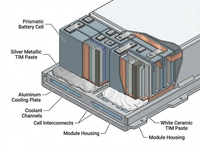
All thermal pastes conduct heat. That is their function. The term “conductive thermal paste” creates a terminology problem. It conflates two separate properties: thermal conductivity and electrical conductivity. Every thermal paste transfers heat. Only some carry electrical current.
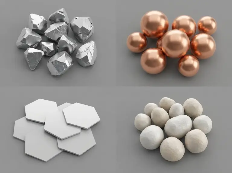
The engineering decision turns on that second property. An electrically conductive paste contains metallic fillers — silver, copper, or aluminum. These fillers form pathways for electron flow. An electrically non-conductive paste uses ceramic fillers — alumina, boron nitride, or zinc oxide. These fillers transfer heat through phonon conduction and block electron flow. Conflating the two terms leads to miscalibrated risk assessments. In EV battery pack design, it produces specifications that fail regulatory review.
For the applications this article covers — EV battery packs, energy storage systems, medical devices, and industrial electronics — non-conductive paste is the defensible default. Conductive paste is justifiable only in one situation: paste contact with any live conductor has been eliminated by verified geometry, not assumed. Four variables determine which case applies: voltage exposure, enclosure seal integrity, thermal resistance budget, and applicable regulatory requirements.
This article does not cover PC gaming paste rankings, application technique comparisons, or thermal paste versus thermal pad trade-offs. For a broader overview, see the different types of thermal pastes guide. All thermal conductivity ranges below are indicative only. Verify specific product values against supplier TDS and independent test data before using them in engineering specifications. Material selection for medical devices and high-voltage energy storage systems requires independent safety assessment against applicable regulations.
Thermal and Electrical Parameters by Filler Type
Filler type determines thermal conductivity and electrical isolation characteristics. The thermal performance gap between metallic and ceramic fillers also closes more than most engineers expect at equivalent filler loadings. The tables below support pre-screening decisions based on parameter ranges, not brand familiarity.
One important note before reading the tables. Filler class alone does not determine electrical classification. Formulation, loading level, and carrier matrix all affect final volume resistivity. Always verify against supplier TDS.
Electrically Conductive Fillers: Silver, Copper, Aluminum
| Filler Type | Typical Thermal Conductivity (W/m·K) | Electrical Isolation Characteristic | Electrical Classification |
|---|---|---|---|
| Silver-filled | 4–6 (conventional formulations; verify against supplier TDS) | Electrically conductive — high leakage risk on live conductor contact | Electrically conductive |
| Copper-filled | Intermediate between silver and aluminum; varies with particle geometry and loading — verify against supplier TDS | Electrically conductive — significant leakage risk | Electrically conductive |
| Aluminum-filled | Typically below 5 W/m·K (verify against supplier TDS) | Electrically conductive to semi-conductive — not an isolation substitute | Electrically conductive |
Silver-filled pastes reach the highest thermal conductivity in this class. The high metallic filler loading drives both thermal performance and low resistivity. These two properties are coupled. Switching filler class is the only way to decouple them.
Electrically Non-Conductive Fillers: Alumina, Boron Nitride, Zinc Oxide
| Filler Type | Typical Thermal Conductivity (W/m·K) | Electrical Isolation Characteristic | Electrical Classification |
|---|---|---|---|
| Alumina (Al₂O₃) | 1–4 (depends on particle size and loading) | Electrically non-conductive — high isolation margin; verify volume resistivity against supplier TDS | Electrically non-conductive |
| Boron nitride (h-BN) | 3–8 (highly loading-dependent; requires >40 vol% loading to reach upper range in well-engineered formulations; verify against supplier TDS) | Electrically non-conductive — highest isolation margin in ceramic filler class; verify TDS | Electrically non-conductive |
| Zinc oxide (ZnO) | Lower than alumina and boron nitride; used as a secondary filler, not a primary thermal contributor | Electrically non-conductive — lower isolation margin than alumina or BN; secondary filler use only | Electrically non-conductive |
Boron nitride is the highest-performing ceramic filler in this class. At sufficient loading — typically above 40 vol% in well-engineered formulations — BN-filled pastes can approach the conductivity of lower-specification metallic pastes. This outcome is formulation-dependent. It is not a guaranteed property of the filler class. The resistivity advantage of ceramic fillers over metallic fillers spans many orders of magnitude.
All values in both tables are representative ranges based on filler chemistry. Actual values are formulation-specific. Verify against supplier TDS before using these ranges as specification inputs.
When the Conductivity Gap Actually Matters
The thermal gap varies by filler selection. It also narrows more than most engineers expect. A high-performing BN paste versus a moderate copper-filled paste may show limited junction temperature difference. This is true when bond line thickness is equivalent. The actual delta depends on power density, bond line thickness, and the broader thermal resistance stack. Confirm it through thermal modelling for the specific application.
A high-specification silver paste versus a standard alumina paste is a different situation. That gap materially affects junction temperature in tight thermal resistance budgets. Two conditions determine the decision. The first is how tight the thermal budget is. The second is whether the application geometry creates genuine short-circuit exposure. When both conditions are present, the tradeoff is real. When only one applies, the decision simplifies.
The Misconception That Distorts Selection Decisions
Electrically conductive paste is not categorically dangerous. Risk depends on geometry, voltage exposure, and paste migration probability. Engineers must assess these variables for each specific application. A uniform risk classification does not apply across all cases.
Paste-related field failures trace to specific geometry conditions. Paste electrical class, as an isolated factor, is not the cause. Avoiding conductive paste in applications with no bare conductor exposure costs thermal performance. It does not reduce real risk.
Three variables appear in every actual short-circuit risk scenario. The first is bare metallic conductors within paste migration range. The second is sufficient voltage to drive current through any bridged path. The third is paste viscosity that permits migration under thermal cycling or vibration. Fine-pitch SMD pad arrays are a genuine risk scenario. High-voltage copper bus bars without encapsulation are a genuine risk scenario. A sealed CPU IHS with no exposed traces beneath it is not.
EV battery packs are the most complex case. Individual cell casings may be sealed. But the aggregate system contains high-voltage connections and BMS boards with exposed pads. Sustained thermal cycling drives paste migration over thousands of hours. In that environment, the risk is not theoretical. In a fully potted industrial motor controller with no exposed conductors in the paste contact zone, the same paste carries no meaningful electrical risk.
This geometry-based assessment supplements mandatory regulatory requirements. It does not replace them. Verify those requirements independently for each application and jurisdiction.
Default Paste Selection by Industry
Which paste class is defensible by default depends on the industry. Each sector has a distinct voltage exposure profile, regulatory environment, and enclosure geometry. The defaults below are the justifiable starting positions under typical conditions. Exceptions require documented engineering verification.

EV Battery Packs: Voltage Isolation Requirements
Non-conductive paste is the defensible default for EV battery pack applications. Pack-level voltages in current-generation platforms typically fall in the 400 V to 800 V range. Verify actual system voltage against specific vehicle architecture specifications. At these voltage levels, resistive bridging through conductive paste is a safety-relevant failure mode.
BMS boards, cell interconnects, and bus bar assemblies create multiple locations where paste migration can reduce creepage and clearance distances. The applicable standard is IEC 60664 or FMVSS 305 / 305a, depending on vehicle program timing and scope. A justified exception applies only when paste is confined to a hermetically sealed, non-voltage-bearing subassembly. That subassembly must have no internal live surfaces within paste range.
Energy storage systems for grid or commercial use share the same high-voltage constraint. Non-conductive paste is the defensible default for any zone near BMS boards, cell monitoring ICs, or bus connections. Conductive paste may be justified in thermally-bonded heat spreader interfaces within fully enclosed, non-serviceable submodules. Paste-to-conductor contact must be eliminated by verified design — not assumed.
Medical Devices: IEC 60601-1 and Creepage Constraints
When a thermal interface material occupies or crosses an isolation boundary in a medical device, it falls under IEC 60601-1 creepage and clearance requirements. Those requirements are set by working voltage, pollution degree, and insulation class.
Non-conductive paste is the defensible default for most medical device applications under these isolation requirements. Exceptions require explicit compliance documentation.
If a paste reduces effective creepage distance below the IEC 60601-1 minimum, the assembly may not meet compliance requirements. This applies regardless of intent. Whether a specific paste affects compliance depends on its position relative to isolation boundaries, working voltage, pollution degree, and insulation class. A qualified medical device compliance engineer must make that determination. For industrial electronics, IEC 60664-1 governs insulation coordination and imposes similar creepage constraints.
Industrial Electronics: Vibration and Paste Migration Risk
Industrial electronics present the widest risk variance of any sector. Non-conductive paste is the conservative default for open-frame boards, vibration-prone environments, and enclosures with leakage probability above the design threshold.
Vibration accelerates paste migration from the bond line to adjacent areas. In open-frame industrial control boards with close trace spacing, migration-driven bridging over service life is a real failure mode. Conductive paste is justifiable in sealed industrial modules. Paste must be confined to a closed thermal interface. No adjacent exposed conductors can be present. Operating voltage must remain below the threshold where resistive bridging creates a hazard. Verify enclosure protection class against the applicable standard for your specific design.
Application geometry and regulatory environment determine the paste class. What determines how long that choice holds up is a different set of variables.
Long-Term Reliability: Pump-Out and Filler Aging
Neither paste class categorically outperforms the other on longevity. Degradation mode differs by filler type. Service life is formulation-specific within each class.
Consider a sealed EV submodule running through several hundred thermal cycles annually. The question is not which paste class looks better on a datasheet. The real question is which degradation mechanism dominates. The candidates are filler oxidation, carrier fluid volatilization, and bond-line pump-out. The answer depends on temperature, cycling rate, and geometry. No universal answer exists. Resolving it requires data at application-representative conditions.
Metal-filled pastes — silver and copper formulations in particular — may face filler oxidation at elevated temperatures over extended service life. Oxidation is a known degradation mechanism for metallic filler particles. It increases interfacial thermal resistance between particles. This degrades bulk thermal conductivity over time. The effect is formulation-dependent. Oxide-barrier coatings and carrier fluid selection can mitigate it. Verify these properties against supplier aging data.
Ceramic-filled pastes — alumina and boron nitride — are chemically stable at typical electronics operating temperatures. Their primary degradation mechanisms are carrier fluid volatilization and pump-out under repeated thermal cycling. Pump-out rate depends on paste viscosity, bond line thickness, and thermal strain. Filler type is not the primary driver. Low-viscosity formulations of either class pump out faster under high-cycle conditions.
For applications with aggressive thermal cycling profiles, verify aged thermal interface material durability in EV batteries at application-representative cycle counts. As a TIM supplier to EV and ESS programs across multiple markets, Trumonytechs recommends treating initial W/m·K values as screening filters. Aged performance data predicts field behavior. Initial datasheet values do not.
A Four-Variable Selection Framework
“Non-conductive is always safer” dominates generic guidance. It produces correct answers in some situations. It produces unnecessarily conservative specifications in others. Four application variables resolve the ambiguity.
This framework is based on risk geometry assessment only. It does not replace mandatory regulatory requirements. Verify applicable standard compliance independently for each application. Regulatory obligations take precedence over any framework output where they conflict.
Variable 1: Voltage Exposure Level
Assess whether any live conductor sits within the paste migration zone during the full assembly lifetime. The migration zone includes the initial bond line area and the full perimeter reachable under thermal cycling. If voltage exposure is absent by verified geometry — not assumed — paste electrical conductivity is not a safety constraint.
Variable 2: Enclosure Seal Integrity
Assess whether the assembly is sealed against paste migration. Enclosures with no internal pathways from the TIM zone to live conductors reduce migration risk substantially. Open-frame assemblies retain migration risk regardless of enclosure rating.
Variable 3: Thermal Resistance Budget Tightness
Quantify the maximum permissible junction-to-ambient thermal resistance. If a mid-range ceramic paste fits within that budget, the performance advantage of a metallic paste does not justify the electrical risk. If the budget requires the highest available thermal conductivity and no ceramic formulation closes the gap, the performance argument strengthens.
Variable 4: Applicable Regulatory Requirements
Identify whether IEC 60601-1, IEC 60664, or FMVSS 305 / 305a impose electrical isolation requirements for the application zone. UL 746C may apply to material qualification and aging assessment. It does not directly drive paste electrical class selection. Where isolation requirements apply, verify through compliance review whether they constrain thermal interface material selection. Regulatory requirements override engineering judgment.
| Voltage Exposure | Enclosure Sealed | Budget Tight | Regulatory Mandate | Justified Default |
|---|---|---|---|---|
| Yes | No | No | Yes | Non-conductive |
| Yes | No | Yes | Yes | Non-conductive |
| Yes | Yes | Yes | No | Non-conductive preferred; exception requires geometry verification |
| No | Yes | Yes | No | Conductive justifiable; verify migration path is eliminated by design |
| No | Yes | No | No | Non-conductive preferred; no performance justification for switching filler class |
| No | No | Yes | No | Non-conductive preferred; assess migration risk before considering conductive alternatives |
Conclusion
Electrically conductive and non-conductive thermal pastes serve different risk profiles. The selection logic that applies in one sector does not transfer automatically to another. The four-variable framework — voltage exposure, enclosure seal integrity, thermal resistance budget, and regulatory requirements — produces defensible specifications. It works because it evaluates actual application conditions, not category labels.
A recurring selection error in EV battery and ESS programs is not reckless use of conductive paste. It is reflexive avoidance of higher-performance options in sealed, voltage-free zones. The electrical risk does not exist in those zones. The thermal performance cost does. Match the paste class to the geometry and the regulation.
If your program involves thermal interface material selection for EV, ESS, or industrial power applications, contact Trumonytechs through the Thermal Interface Materials engineering page to discuss your specific application requirements.
FAQ
Does electrically conductive paste deliver significantly better thermal performance?
The gap is real but smaller than most engineers expect. A high-specification silver paste and a well-engineered BN formulation at high filler loading can reach overlapping thermal conductivity values. The performance gap that materially affects junction temperature is between high-specification metallic paste and basic alumina paste — not between the filler classes as a whole. Confirm the actual delta via thermal modelling for your specific bond line and power density.
When is conductive paste justifiable in a high-voltage EV application?
Only when paste contact with any live conductor is eliminated by verified geometry, not assumed. In hermetically sealed submodules with no BMS boards, cell interconnects, or bus bars within paste migration range, the electrical risk geometry changes fundamentally. That exception requires documented design verification. It must also be assessed independently of regulatory obligations, which apply regardless of geometry conclusions.
Does IEC 60601-1 restrict thermal paste in medical devices?
Not by material class name, but its creepage and clearance requirements apply to any material occupying an isolation zone — including thermal paste. If a paste reduces effective creepage below the applicable minimum, the assembly may not meet compliance requirements regardless of intent. Whether a specific paste affects compliance depends on its position relative to isolation boundaries, working voltage, and insulation class. A qualified compliance engineer must make that determination.
Does conductive or non-conductive paste last longer?
Neither class categorically outperforms the other. Metal-filled pastes may face oxidative filler degradation at elevated temperatures. Ceramic-filled pastes are more chemically stable but vulnerable to carrier fluid volatilization and pump-out under high thermal cycling rates. Both effects are formulation-specific. For aggressive cycle profiles, request aged thermal conductivity data from your supplier. Initial datasheet values are screening filters, not reliability guarantees.
