
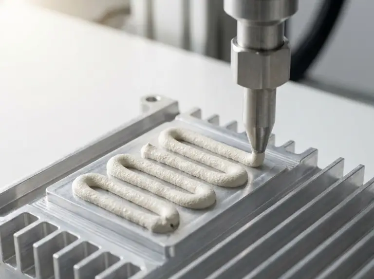
Ceramic thermal paste — the engineering-standard term is ceramic-filled thermal grease or ceramic-based thermal compound — belongs to the broader category of thermally conductive grease and related thermal interface materials (TIMs). It fills microscopic air gaps between heat-generating components and heat-dissipating surfaces. This article addresses material selection decisions for thermal design engineers and EV/energy storage procurement teams.
This article does not apply to consumer PC gaming builds, desktop CPU cooler mounting procedures, or retail product comparisons.
In most cases where electrical non-conductivity is a hard system constraint and thermal conductivity requirements fall within the ceramic performance ceiling — a range that covers most EV battery module gap-filling requirements but falls short of what SiC and IGBT switching applications demand — ceramic-filled TIM is typically the appropriate choice. It is generally the wrong choice when heat-flux density exceeds what ceramic fillers can handle.
What Ceramic Thermal Paste Is
Ceramic-filled thermal grease is a TIM category defined by inorganic ceramic particles dispersed within a silicone or polymer carrier matrix. Common ceramic fillers include alumina (Al₂O₃), boron nitride (BN), and zinc oxide (ZnO), each contributing differently to thermal and electrical properties depending on particle morphology and loading percentage.
Understanding how ceramic performance compares across different types of thermal pastes starts with the conductivity range: approximately 1–4 W/m·K for most ceramic-filled formulations, with high boron nitride content or hybrid multi-filler systems reported to approach 5–6 W/m·K under optimized formulation conditions.
How Ceramic Fillers Build a Thermal Pathway
Ceramic filler particles create thermal conductivity in grease through percolation network formation, subject to particle loading, size distribution, and morphology. At sufficient filler concentration, particles contact adjacent particles. This typically forms continuous chains that conduct phonons — the primary heat carriers in ceramic materials — from the component surface to the heatsink.
Alumina offers moderate conductivity and relatively lower material cost compared with boron nitride or silver-based fillers, subject to formulation and market pricing. Boron nitride adds directional thermal performance and superior electrical insulation. At controlled particle sizes, zinc oxide achieves higher packing density, which makes it useful in hybrid filler formulations where alumina or BN serves as the primary conductivity contributor.
Typical thermal conductivity for ceramic-filled thermal grease ranges from approximately 1–4 W/m·K, with high boron nitride content or hybrid multi-filler systems reported to approach 5–6 W/m·K under optimized formulation conditions. Formulators cannot arbitrarily increase filler loading without degrading dispensability and increasing thermal resistance through poor wet-out behavior.
This range defines the performance ceiling engineers should evaluate before specifying ceramic TIM for any application. Thermal conductivity values cited here represent industry-typical ranges; specific product performance varies by formulation and should be verified against supplier-provided TDS data validated under target application conditions.
That thermal conductivity ceiling, however, is only half the selection argument; the electrical behavior of the filler system drives the other half.
Electrical Non-Conductivity: Properties and Limits
Electrical non-conductivity in ceramic-filled TIM is a genuine and quantifiable material property, subject to filler chemistry and formulation purity. Volume resistivity for alumina-filled or boron-nitride-filled thermal grease typically falls within 10¹²–10¹⁴ Ω·cm under dry, ambient test conditions. Confirm specific values against the supplier TDS for the product under evaluation. This positions ceramic TIM as electrically insulating under typical measurement conditions, not merely “less conductive” than metal-based alternatives.
In our experience evaluating TIM failure modes across EV battery module and power electronics programs — Trumonytechs has supported thermal management qualifications in over 56 countries since the Trumony Group was established in 2006 — resistivity mismatches between specified and delivered materials have appeared repeatedly as an underweighted risk in early-stage design reviews. Published power module failure analyses have also identified TIM resistivity mismatches as confirmed failure root causes, particularly in assemblies where paste migration reaches live conductor areas. The distinction between a ceramic TIM with verified resistivity data and a loosely labeled “non-conductive” compound lacking third-party electrical characterization represents a real design risk — non-conductivity is a specified parameter, not a marketing claim. Always require measured volume resistivity values in the supplier datasheet before specifying for any electrically sensitive assembly.
Engineers comparing thermal grease vs thermal paste categories often treat all “non-conductive” labels as equivalent — that distinction matters far more in dense power module assemblies than in standard gap-filling applications.
Metal-based TIMs — those using silver, copper, or indium particles — offer higher thermal conductivity ceilings, commonly reaching 6–12 W/m·K depending on formulation, enough to handle most power module junction-to-case budgets that ceramic formulations cannot. That conductivity advantage comes with a tradeoff: metal-based TIMs are electrically conductive. Paste migration, overapplication, or mechanical displacement can bridge exposed pads, pins, or traces. In dense multi-chip power modules and IGBT assemblies, this creates a short-circuit risk that ceramic-filled TIM typically eliminates by design.
Non-conductivity tends to become a hard engineering constraint — rather than a preference — in these conditions:
- Exposed conductor areas exist within the paste application zone
- Power module substrate geometry does not fully isolate bond pads
- BMS circuit boards in EV battery modules require paste application near signal-level traces
- Dense multi-die packaging with no physical barrier between dies and paste
With both the thermal and electrical parameters in view, the comparative picture against other TIM categories becomes clearer.
Ceramic vs. Metal-Based, Carbon-Based, and Silicone-Only TIMs
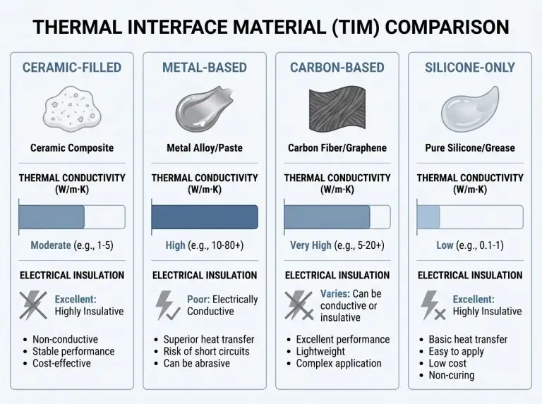
Unlike metal-based, carbon-based, and silicone-only TIMs, ceramic-filled thermal grease occupies a specific performance band across four engineering dimensions that typically determine selection outcome in industrial and EV applications. All values in the table below represent industry-typical ranges subject to formulation-specific variation.
| Engineering Dimension | Ceramic-Filled TIM | Metal-Based TIM | Carbon-Based TIM | Silicone-Only TIM |
|---|---|---|---|---|
| Thermal conductivity ceiling | ~1–6 W/m·K (4 W/m·K conservative; up to ~6 W/m·K reported for high-BN formulations) | ~6–12 W/m·K (silver-filled formulations at upper range) | ~5–9 W/m·K (reported for CNT/graphene-enhanced formulations) | ~0.2–1.0 W/m·K (filler-content dependent) |
| Electrical insulation | High (10¹²–10¹⁴ Ω·cm typical; verify against TDS) | Electrically conductive | Varies; carbon can be semi-conductive | Insulating, but lower thermal return |
| Long-term pump-out and oil bleed-out risk | Moderate; formulation and bond-line dependent | Higher displacement risk in high-shear conditions | Varies by carrier | Low risk; minimal filler migration |
| Handling safety | No special controls required | Skin/surface contamination risk | Low toxicity; some dusting concern with dry forms | No special controls required |
Pump-out (thermal-cycling-driven TIM displacement) and oil bleed-out are two distinct long-term failure mechanisms that should be evaluated separately. Risk ratings above are relative comparisons based on typical formulations; absolute risk level depends on bond-line thickness, thermal cycling rate, and substrate surface roughness. Carbon-based conductivity range represents published values for CNT/graphene-enhanced formulations; verify against specific product TDS.
Those four dimensions narrow the field; the decision matrix below converts them into actionable selection criteria, including gap pad thermal conductivity considerations where phase-change or pad alternatives are relevant.
When to Use Ceramic TIM and When to Switch
When system conditions include an electrical isolation hard constraint and thermal conductivity requirements fall within 1–6 W/m·K, ceramic-filled TIM is generally the appropriate choice, subject to verification of specific product parameters against application requirements.
Select ceramic-filled TIM when:
- Thermal conductivity requirement falls within 1–6 W/m·K and is confirmed against junction temperature budget
- Electrical non-conductivity is a hard design constraint due to exposed conductor proximity
- Application involves sealed, long-service-life deployment with limited or no rework access
- Operating environment includes vibration or thermal cycling where non-migrating, stable TIM behavior is required
- Regulatory or safety standards require verified volume resistivity in the TIM layer
Select a different TIM category when:
- Heat-flux density at the interface demands thermal conductivity above 6 W/m·K
- Assembly process uses controlled bonding pressure compatible with phase-change materials or thermal pad selection criteria, which typically offer better bond-line control under compression
- Application is serviceable consumer hardware where cost-optimized silicone-only TIM is thermally sufficient
- System architecture fully isolates all conductors from the TIM application zone, removing the insulation constraint and allowing metal-based TIM for maximum conductivity
- Thermal pad or phase-change film provides better process control than dispensed grease for the given assembly tolerance stack
This matrix is a starting framework. Every selection decision should be confirmed against a specific product TDS, validated through thermal resistance measurement in the actual assembly, and reviewed against applicable certification requirements.
What the matrix does not address is how ceramic TIM performs over service life — a separate and equally consequential question for industrial and EV deployments.
Long-Term Stability in Industrial, EV, and Energy Storage Deployments
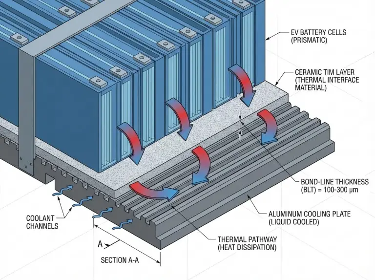
At the formulation level, industrial and automotive-grade ceramic TIM typically operates across −40 °C to +125 °C under standard silicone base chemistry, with some high-temperature formulations extending to +150–175 °C depending on carrier polymer and filler compatibility; temperature range claims should be verified against the supplier TDS. Pump-out and oil bleed-out are two distinct long-term failure mechanisms that should be evaluated separately — pump-out risk depends on carrier viscosity, bond-line thickness, and thermal cycling conditions, while oil bleed-out risk is formulation-dependent and typically minimized in high-quality ceramic TIMs with controlled oil-separation characteristics.
For any EV battery thermal management and industrial applications with long-service-life requirements, specifying a TIM with published thermal cycling stability data — not only initial thermal conductivity — is the appropriate procurement practice.
Conclusion
Across EV battery module qualifications and industrial power electronics programs, the most consistent specification error is not choosing the wrong thermal conductivity — it is failing to specify and verify the electrical resistivity parameter before finalizing the ceramic thermal paste selection. Require measured volume resistivity data from your supplier, confirm it against your system’s isolation requirements, and validate under assembled conditions before production release. That discipline separates a reliable thermal design from a field failure waiting for the right stress condition.
As a national high-tech enterprise with R&D partnerships including Shanghai Jiao Tong University, our engineering team works across EV, ESS, and industrial power electronics programs spanning more than 56 countries. If your program involves ceramic TIM selection for EV or industrial power applications, contact us through our Thermal Interface Materials engineering page to discuss your specific application.
FAQ
Is ceramic thermal paste electrically non-conductive?
Yes, ceramic thermal paste — specifically ceramic-filled thermal grease — is genuinely electrically non-conductive, with volume resistivity typically in the range of 10¹²–10¹⁴ Ω·cm under dry, ambient conditions. Confirm the specific value against the supplier TDS, and do not rely on TIM as the sole isolation barrier in a safety-critical assembly without validating under assembled conditions.
Does ceramic thermal paste work on EV battery packs or power modules?
Ceramic-filled TIM is a strong match for battery module gap-filling where thermal conductivity requirements fall within 2–5 W/m·K and electrical isolation is needed between cell surfaces and cooling plates. For high-flux IGBT or SiC module applications demanding above 6–8 W/m·K, the ceramic ceiling may be insufficient and carbon-based or metal-based TIM categories warrant evaluation.
How does ceramic thermal paste conductivity compare to metal-based TIMs?
Ceramic-filled thermal grease typically delivers 1–6 W/m·K depending on filler type and loading, while metal-based TIMs — particularly silver-filled formulations — commonly reach 6–12 W/m·K. The conductivity gap is real and consequential for high heat-flux applications, but metal-based TIMs are electrically conductive, which may be disqualifying where exposed conductors are present in the application zone.
When is a ceramic-filled TIM not thermally sufficient for high heat-flux applications?
The ceramic TIM thermal ceiling typically becomes limiting when conductivity requirements exceed approximately 5–6 W/m·K. Carbon-based or metal-based TIM categories should then be evaluated. The threshold is not absolute — bond-line thickness, interface pressure, and substrate surface finish all shift it — but applications pushing above 6 W/m·K should not default to ceramic TIM without a verified thermal resistance calculation.
Does ceramic TIM support IATF 16949 compliance?
IATF 16949 is a supplier quality management system certification, not an inherent material property. Suitability depends on the supplier’s certification scope, dispensing process documentation, material traceability, and application-specific validation covering thermal cycling and environmental exposure for the target vehicle platform. Consult the OEM supplier approval process and the TIM supplier’s quality documentation directly.