
Thermoelectric cooling is ideal for applications requiring precise temperature control in compact, sealed, or vibration-sensitive systems. At Trumonytechs, we specialize in thermal management solutions for environments with limited airflow and where stable, set-and-hold temperature control is critical.
This technology uses electrical current to create a temperature difference between two sides of a module, transferring heat from one side to the other. With no moving parts, thermoelectric cooling is highly reliable for precise temperature regulation.
What Thermoelectric Cooling Is?
Thermoelectric cooling (TEC), also known as Peltier cooling, is a solid-state heat pump powered by DC electricity. One side of the module absorbs heat and becomes cold, while the other side rejects heat and becomes hot.
What it’s not: TEC is not a universal replacement for refrigeration or HVAC systems. It excels in localized, controlled cooling but depends heavily on efficient heat removal from the hot side, often requiring a heatsink or cold plate to dissipate heat effectively.
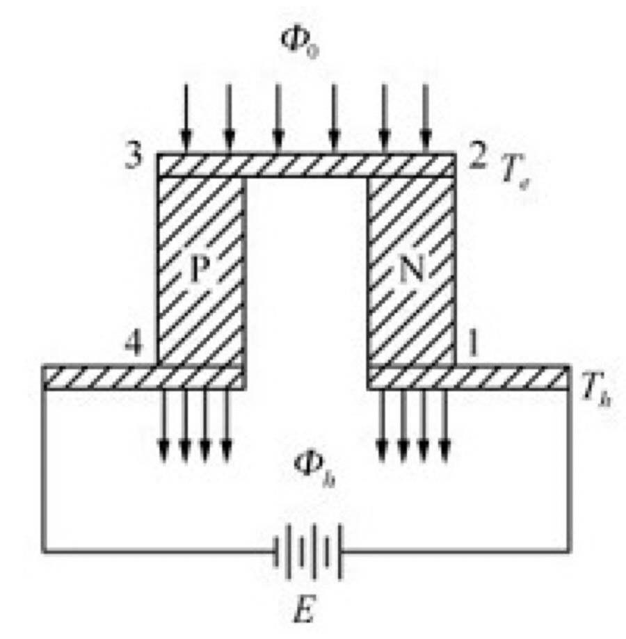
How Thermoelectric Cooling Works?
TEC operates by driving DC current through p-type and n-type semiconductor couples, which transfer heat from the cold side to the hot side. The direction of heat flow depends on the current’s polarity.
The Peltier effect occurs when an electric current passes through a junction of two different materials. One side cools down by absorbing heat, while the other side heats up by releasing it. Reversing the current swaps the hot and cold sides, allowing the same module to both heat and cool.
In practice, three heat mechanisms coexist:
- Peltier effect (useful): Pumps heat from cold to hot.
- Thermal conduction (leakage): Heat flows back from hot to cold.
- Joule heating (I²R): Heat generated inside the module.
Good designs maximize the Peltier effect while minimizing leakage and resistive losses.
Inside a TEC Module: Key Parts and Heat Paths
A TEC module consists of multiple p/n couples connected electrically in series and thermally in parallel. This design balances practical voltage/current levels with efficient heat flow.
Typical components:
- Semiconductor pellets (p-type/n-type): Create the Peltier effect. Common material: Bi₂Te₃ for near-room-temperature TECs.
- Metal interconnects: Carry current between couples. Common material: Copper.
- Ceramic substrates: Electrically insulate and spread heat. Common material: Alumina (Al₂O₃).
Important note: A TEC doesn’t eliminate heat—it moves it. The hot side must dissipate both the heat absorbed from the cold side (Qc) and the electrical input power. This is often achieved using a heatsink or cold plate, which provides a flat, thermally efficient surface for heat rejection.
Main Types of Thermoelectric Coolers and Their Uses
The type of TEC affects its temperature difference, heat pumping capacity, power demand, and integration complexity.
Single-Stage TEC – General-Purpose Cooling
- Description: One layer of couples for moderate temperature lift and practical power use.
- Best for: Stable setpoints, small/medium heat loads, and simpler packaging.
- Limitations: Not suitable for extreme temperature differences (ΔT) at significant heat loads, as efficiency drops with rising ΔT.
Multi-Stage (Cascade) TEC – Extreme ΔT
- Description: Stacks multiple stages to achieve higher ΔT for aggressive below-ambient targets with small heat loads.
- Best for: Precision instruments and demanding low-temperature setpoints.
- Trade-offs: Higher power consumption, increased internal resistance, and stricter heat rejection requirements.
Thin-Film / Micro TEC – Fast, Localized Cooling
- Description: Uses MEMS-style fabrication for small, low-thermal-mass coolers.
- Best for: On-chip or micro-optoelectronic cooling in tight spaces.
- Limitations: Lower heat pumping capacity and higher sensitivity to interface quality.
| Item | Single-Stage | Multi-Stage | Thin-Film / Micro |
|---|---|---|---|
| Typical Goal | Moderate ΔT + usable Qc | Extreme ΔT at lower Qc | Fast spot cooling, tiny area |
| Power Demand | Low–moderate | Higher | Varies, often constrained |
| Integration | Easier | More complex | High (interfaces, mounting) |
Key Performance Metrics (ΔTmax, Qmax, COP, ZT)
TEC performance depends on operating conditions like hot-side temperature, heat load, and drive current. Key metrics include:
- ΔTmax: Maximum temperature difference at nearly zero heat load. Adding heat to the cold side reduces achievable ΔT.
- Qmax: Maximum heat pumping capacity at ΔT ≈ 0°C. As ΔT increases, Qc decreases.
- COP (Coefficient of Performance): Efficiency ratio (Qc / Pin). COP varies with ΔT, current, and hot-side temperature.
- ZT (Figure of Merit): Material efficiency indicator. Higher ZT supports better COP and/or higher ΔT.
Practical Selection & Integration Basics
TEC performance often suffers due to system bottlenecks rather than module limitations. At Trumonytechs, we focus on these key constraints:
- Hot-Side Heat Rejection: If the hot side overheats, ΔT and COP drop. Use a well-designed heatsink or coldplate to keep the hot side cool under worst-case loads.
- Thermal Interface Resistance: Even small contact resistance can dominate the thermal stack. Use proper TIM, flat surfaces, and adequate mounting pressure to minimize losses.
- Heat Backflow: Heat can leak back through conduction or surrounding structures. Minimize bypass paths with smart mechanical design and insulation.
Mini checklist:
- Define your heat load (Qc) and target temperature (or ΔT).
- Choose a TEC using datasheet curves at realistic hot-side temperatures.
- Size the hot-side cooling for (Qc + Pin), not just Qc.
- Plan for stable DC control with current limits and sensor feedback.
Conclusion
Thermoelectric cooling offers a compact, solid-state solution for precise temperature control, especially where traditional methods fall short. Its performance depends on hot-side heat rejection, interface quality, and heat leakage control—not just the module’s specs.
At Trumonytechs, we approach TEC as a system design challenge. By defining load and temperature targets, analyzing datasheet curves, and optimizing the heat path and control loop, we ensure the module delivers on its promise.
FAQ
Can TEC cool below ambient temperature?
Yes, if the hot side efficiently rejects heat. Excessive hot-side temperature reduces ΔT headroom.
Why does TEC efficiency drop at high ΔT?
Higher ΔT requires more power, while useful heat pumping decreases. Joule heating and conductive backflow dominate at high lifts.
Can TEC be used for heating?
Yes, reversing the DC polarity swaps the hot and cold sides, enabling bidirectional temperature control.
How can I tell if my TEC is undersized?
If it can’t maintain the target temperature despite strong hot-side cooling, it’s likely undersized for Qc or ΔT. Check the datasheet curve for your conditions.
What causes unstable temperature control?
Instability often stems from control tuning or sensor placement. Poor thermal contact, slow sensors, or aggressive control loops can cause oscillations.
