
Custom ESS Cooling Solutions: Liquid Cold Plates, Tubes and Manifolds
ESS cooling solutions from Trumonytechs are the heat-path and coolant-routing parts in an energy storage battery system: cold plates, aluminum cooling tubes, distribution manifolds and thermal interface materials. Cold plate configuration is aligned to cell format at design review, and channel geometry follows maximum heat load and allowable pressure drop. We supply cold plates designed to your pack geometry, with CFD reviewed before tooling and volume production released after sample sign-off, while thermal interface materials come from listed model ranges.
Send the cell format and the maximum heat load per cell and per pack: the cold plate configuration is aligned to the first, and the second is the primary input to flow path sizing.
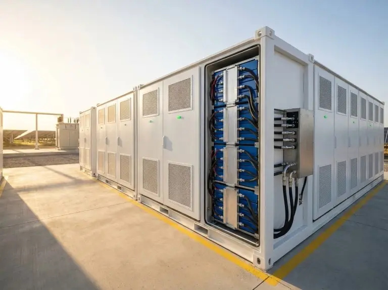
Liquid or Air: Which Energy Storage Installations Need Liquid Cooling
Energy storage installations almost always need active liquid cooling when they run high C-rate cycles, sit outdoors or in containers, or operate at utility scale. At pack level, liquid cooling is chosen over air when the cell-to-cell ΔT target falls below 3–5 °C or heat load per unit area passes a threshold.
One of two triggers for choosing liquid cooling over air: a cell-to-cell ΔT target tighter than this band.
- Passive limits hold
Natural convection or a heat sink already manages the heat load.
- No place for loop hardware
The layout has no room for a pump, reservoir and heat exchanger.
- Fluid and metal clash
The working fluid is incompatible with aluminum or copper.
Lower-density backup systems at moderate ambient temperatures may be adequately served by air cooling, and we check that at the initial technical review rather than defaulting to a liquid loop. Grid-scale storage calls for high-reliability cooling, C&I systems for tight temperature control, and solar and wind storage for tolerance of variable charge rates and wide ambient ranges. Air, liquid and immersion options are compared in our guide to industrial energy storage thermal management.
ESS Cooling Solutions by Cell Format: Cold Plate Types and Coolant Loop Parts
ESS cold plates are configured to cell format at the design review, and the coolant-routing parts and interface materials around them are covered on the four cards below.

Snake tube cold plates — cylindrical cells
A serpentine path runs in direct axial contact with the cell casings, with flow rate, tube diameter and contact geometry sized to the confirmed heat load and uniformity target.

Microchannel cold plates — pouch cells
More heat transfer area per unit of plate thickness suits strict Z-height budgets and uniform temperature across the cell face; loop cleanliness is confirmed during scoping.
Cooling tubes, manifolds and brazed assemblies
Aluminum cooling tubes, liquid distribution manifolds, brazed cooling assemblies and thermal interface integration structures carry coolant between battery modules and the heat exchange system. Their dimensions, joint types and pressure ratings are not published on this page, so state your envelope and connection type in the RFQ.
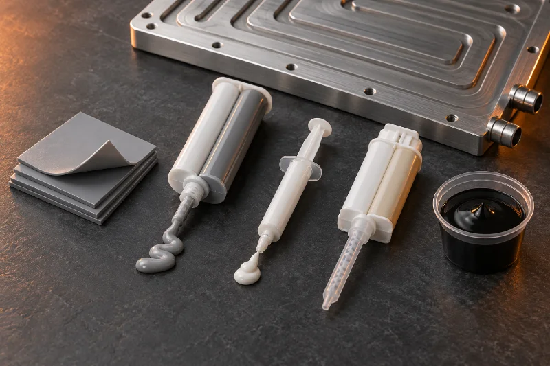
Thermal interface materials
Gap pads, dispensable gels, silicone grease, structural adhesive and potting compound, each with its own listed position in the table below.
For prismatic cells, the cold plate construction is confirmed at the first design review. Figures are schematic; built sizes on the water cooling plate page are examples, not limits.
For cylindrical and pouch cells the format already points to a construction: snake tube plates for cylindrical cells, microchannel plates for a pouch pack with a tight Z-height budget. A wrong type chosen before tooling adds thermal resistance, pressure-drop penalties and interface compatibility problems, so we align the configuration to cell format at the first design review.
Coolant Mix, Alloy and Interface Material for ESS Cold Plates
Coolant chemistry needs checking early for an ESS cold plate, because the water-glycol ratio or alternative fluid changes thermal conductivity, viscosity and pressure drop targets. The ESS cold plate specification lists 3003 aluminum and vacuum brazing, while 1060 aluminum and copper appear only in the wider range on the water cooling plate page.
| TIM family | Form | Listed conductivity | Position in an ESS pack | Application | Electrical insulation |
|---|---|---|---|---|---|
| Thermal conductive pad 30101 | Silicone pad, 0.4–10 mm | 1.5–8.0 W/m·K, 5 models | Prismatic or cylindrical cells; snake tube plates | Manual placement; unreinforced or reinforced | Yes; >6 to >12 kV/mm by model |
| Thermal conductive gel 30102 | Two-part silicone gel | 1.5–8.0 W/m·K, 6 models | Gaps that need low assembly stress | Automated dispensing; room-temperature or heat cure | Yes; 8 kV/mm |
| Silicone grease 30108 | Non-curing paste | 3.5–5.0 W/m·K, 3 models | Not specified in model data | Dispensing or printing | Model 0350 only |
| Structural adhesive 30107 | Two-part polyurethane, 1:1 | 2.05 W/m·K (ASTM D5470) | Bonds cells to the cold plate | Full cure 7 days at 23 ± 2 °C | Yes; 14–16 kV/mm |
| Potting compound 30103 | Two-part silicone, hand-mixed | 0.8–4.0 W/m·K, listed models | Module filling, insulation and potting | Mix, degas, pot; room or elevated cure | Yes; 10 kV/mm listed for 0080 |
Conductivity is measured to ISO 22007-2 except for 30107, which is measured to ASTM D5470; ranges cover listed models only. All five families list a UL 94 V-0 flame rating, and the gel, grease and potting series also list a RoHS-compliant formulation.
Pads suit joints placed by hand and can take a reinforcement layer when a large piece needs body strength. Gels suit automated dispensing lines where the cells should see low assembly stress. Choosing among the five families is part of the thermal design review and is not charged separately.
Two compatibility checks come early: aluminum and copper parts stay in separate coolant loops, and the glycol concentration is matched to the plate alloy, since some concentrations accelerate corrosion in some grades.
Tooling, Volume and Late Changes: The Cost Levers in ESS Liquid Cooling
Tooling for ESS cold plates depends on process: a CNC-machined prototype needs no tooling, while a stamped production plate needs a dedicated die. Cold plate type selection also weighs heat load, plate size, available space, production volume and cost. When an input changes after a prototype has been built, the change can cost more time and material than settling it at the design review. Prices and tooling charges are not published on this page; quotes are based on your drawing or boundary dimensions, heat load and expected annual volume.
Cold plate quotes come with DFM feedback at no extra charge: attach the drawing with maximum heat load, coolant mix and expected annual volume.
Supply Scope and the Pump Interface in an ESS Cooling Loop
Trumonytechs parts cover the ESS loop from cold plate to manifold, and the design review ties them to your pump through the pressure-drop budget.
The parts on the cards above, plus the thermal design review and CFD simulation. Container and rack structural parts for liquid-cooled systems also appear in the listed scope; their specifications are not published on this page.
Maximum allowable pressure drop drives channel geometry and flow distribution, so it is confirmed against your pump and system head budget before the first simulation iteration. Inlet temperature and flow rate range define the thermal boundary conditions for that simulation.
EV packs and cross-product selection are covered on the battery pack thermal management page.
Sign-off Gates and Validation Tests Before ESS Volume Production
Cold plate and cooling component projects for ESS pass through five stages, and each stage closes with a client confirmation point. We do not start tooling or fabrication until your engineering team has formally approved the simulation outputs.
Quality system certificates (ISO 9001, IATF 16949) are available on request; specify which you need in your inquiry.
Each cold plate is leak tested with helium, not sampled from the batch.
Mechanical load, thermal performance, flow resistance, internal corrosion and salt spray corrosion.
Leak, pressure and thermal resistance tests plus client-specific documentation before volume release.


Outgoing cold plate inspection adds a CMM check that includes thermal-interface flatness and a hydrostatic burst test above rated working pressure. First article inspection reports and visual and metallographic checks on welds and brazed joints complete the set. Documentation from cold plate development testing is provided for supplier qualification programs. Cold plate development also yields a 2D drawing with key interface dimensions, the flow channel and connector concept, and a CFD thermal and flow evaluation summary, with CNC prototypes tested and iterated before validation.
- Thermal design reviewClient confirms inputs
Feasibility check on cell format, heat load, temperature targets and pack geometry, ahead of any design work.
- CFD simulationClient reviews outputs
Flow distribution, temperature uniformity predictions and pressure drop estimates under the defined inlet conditions, reviewed before tooling.
- Prototype fabricationTimeline confirmed
Begins only after simulation sign-off, with lead time confirmed by cold plate type and geometry.
- Sample validationClient sign-off
Formal sign-off on the validated sample is required before the next stage.
- Volume productionProduction begins
Starts once the validated sample carries your sign-off.
Friction stir welding, vacuum brazing, stamping, extrusion and CNC machining make up the cold plate process range.
The inspection and test lists above cover cold plates. Inspection items and shipping documents for cooling tubes and manifolds are not published on this page, so request them with your RFQ.
What to Send, Prototype Timing and Shipment Documents for ESS Cold Plates
A thermal design review for ESS cold plates starts from five inputs, with maximum heat load as the primary input to flow path sizing and temperature uniformity calculations. Cell format and count, pack dimensions and layout, and the target maximum cell temperature and ΔT complete the brief.
- Maximum heat load, per cell and per pack
- Coolant type and concentration
- Inlet temperature and flow rate range
- Maximum allowable pressure drop
- Interface material constraints from your cell or BMS supplier
- CNC prototypeUsually 2–3 weeks
Lead time for CNC-machined prototype cold plates after design confirmation.
- Tooled prototypeSet at design review
Stamped and other tooled constructions take longer, with the timeline confirmed at the design review.
- Volume productionAfter sample sign-off
Lead time depends on plate geometry, tooling requirements and production scheduling, confirmed once cell format and pack dimensions are defined.
Cold plates are packed moisture-sealed with desiccant, ports are closed with sealing plugs against particle contamination, and large orders ship in wooden crates.
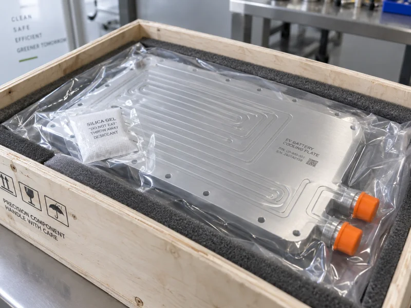
Cold plate shipments come with a certificate of conformance, technical data sheet, mill certificate and packing list. RoHS and REACH declarations and SVHC communication are available on request, and the material composition supports IMDS submission.
ESS Integrator Questions on Cooling Loop Components
Can the ESS cooling review start before our cell supplier locks final parameters?
Yes. Describing your cell type and system-level temperature target is enough to begin a useful technical exchange. Confirmed values can be shared first, and the open variables are identified before scoping proceeds. CFD outputs built on estimated or placeholder values should be expected to change when the final cell parameters are fixed.
Which inputs usually shift late, and what happens when they do?
Coolant type and concentration, and inlet temperature, are the two most likely to move late. Inlet temperature sets the thermal boundary for simulation, and the coolant mix shifts pressure drop targets. A flow path sized on assumed values can miss its uniformity target on the first run, which is why both get flagged for early confirmation.
Do your ESS cooling solutions include the pump and heat exchanger?
Your system integrator or BOS supplier typically provides the pump and the external heat exchanger. Advice on integrating the cold plates, tubes and manifolds with that balance-of-system hardware is given during the thermal design review, at the same stage where the cold plate configuration is aligned to your cell format.
How is consistency held from batch to batch on volume orders?
Key cold plate dimensions run under statistical process control against CPK targets, and each batch ships with a full traceability label. Volume production also starts only from a sample your engineering team has signed off. Equivalent batch controls for tubes and manifolds are not published on this page.
What is the minimum order for ESS cold plates and loop parts?
The minimum depends on stage and process. Cold plate samples and prototypes take flexible quantities; in production, a stamped plate with its own die has a higher threshold than a CNC-machined or FSW plate. Production MOQ is confirmed after the drawing and annual volume forecast are reviewed. Minimums for tubes and manifolds are not published on this page.
Will our UL 9540 or IEC 62933 program accept your quality documents?
Acceptance depends on your program's supplier qualification criteria and should be confirmed early in commercial discussion. Quality system certificates (ISO 9001, IATF 16949) are available on request. UL 9540 covers energy storage systems and equipment, and IEC 62933 covers electrical energy storage systems, so the documents expected from a component supplier should be checked before engagement begins.
Are warranty, payment, shipping and NDA terms published?
Warranty terms, payment terms, third-party inspection, transit times, import duties, after-sales support and NDA terms are not published on this page. Ask for the ones you need with your RFQ. Transit time and duties depend on the destination port and country, and are confirmed in the quote.
